


ASUS P5Q-VM 2-23
NB Voltage [Auto]
Allows you to set the North Bridge voltage. The values range from 1.10V to 1.70V
with a 0.02V interval.
• Setting the CPU PLL Voltage, FSB Termination Voltage, DRAM Voltage and
NB Voltage items to a high level may damage the chipset, memory module
and CPU permanently. Proceed with caution.
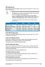
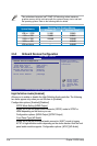
• Values of the CPU PLL Voltage, FSB Termination Voltage, DRAM
Voltage and NB Voltage items are labeled in different colors, indicating the
risk levels of high voltage settings. Refer to the table below for details.
• The system may need better cooling system to work stably under high
voltage settings.
Blue Yellow Purple Red
CPU PLL Voltage 1.50V–1.78V 1.80V–2.00V 2.02V–2.20V N/A
FSB Termination Voltage 1.20V–1.38V 1.40V–1.70V N/A N/A
DRAM Voltage 1.80V–1.98V 2.00V–2.20V 2.22V–2.40V 2.42V–2.70V
NB Voltage 1.10V–1.26V 1.28V–1.40V 1.42V–1.58V 1.60V–1.70V
PCIE SATA Voltage [Auto]
Allows you to set the PCI Express SATA voltage. The values range from 1.50V to
1.80V with a 0.10V interval.
Load-Line Calibration [Auto]
Allows you to select the CPU Load-Line mode. Set to [Disabled] to follow Intel
®
specications, or to [Enabled] to improve CPU VDroop directly.
Conguration options: [Auto] [Disabled] [Enabled]
CPU GTL Reference [Auto]
Allows you to enable or set the CPU GTL voltage reference. Setting a high CPU
voltage may damage the components permanently, and setting a low voltage may
make the system unstable.
Conguration options: [Auto] [0.65x] [0.63x] [0.61x]
CPU Spread Spectrum [Auto]
Set to [Disabled] to enhance FSB overclocking ability or [Auto] for EMI control.
Conguration options: [Auto] [Disabled]
PCIE Spread Spectrum [Auto]
Set to [Disabled] to enhance PCIE overclocking ability or [Auto] for EMI control.
Conguration options: [Auto] [Disabled]