


ASUS P8Z77-V LE PLUS 2-3
Chapter 2
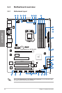
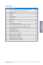
Connectors/Jumpers/Slots Page
1. CPU and chassis fan connectors (4-pin CPU_FAN, 4-pin CHA_FAN1/2/3)
2-25
2. ATX power connectors (24-pin EATXPWR, 8-pin EATX12V) 2-27
3. EPU LED (EPU_LED) 2-21
4. EPU switch 2-18
5. TPU switch 2-17
6. TPU LED (TPU_LED) 2-21
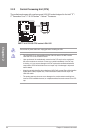
7. Intel
®
CPU socket 2-4
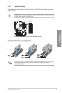
8. DDR3 DIMM sockets 2-5
9. DRAM LED 2-20
10. MemOK! button 2-16
11. USB 3.0 connector (20-1 pin USB3_34) 2-26
12. Marvell
®
Serial ATA 6.0 Gb/s connectors (7-pin SATA 6G_E1 [navy blue]) 2-27
13. Intel
®
Z77 Serial ATA 6.0 Gb/s connectors (7-pin SATA6G_1/2 [gray]) 2-22
14. Intel
®
Z77 Serial ATA 3.0 Gb/s connectors (7-pin SATA3G_1~4 [blue])
2-23
15. Onboard LED (SB_PWR)
2-20
16. BIOS Flashback LED (FLBK_LED)
2-21
17. Clear RTC RAM (3-pin CLRTC)
2-15
18. System panel connector (20-8 pin PANEL)
2-28
19. BIOS Flashback button (BIOS_FLBK)
2-19
20. USB 2.0 connectors (10-1 pin USB3~10)
2-24
21. Serial port connectors (10-1 pin COM1)
2-26
22. Front panel audio connector (10-1 pin AAFP)
2-24
23. Digital audio connector (4-1 pin SPDIF_OUT)
2-25
Layout contents