


ASUS Striker Extreme 2-31
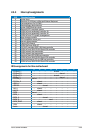
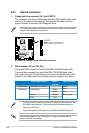
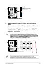
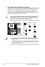
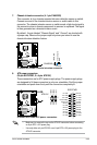
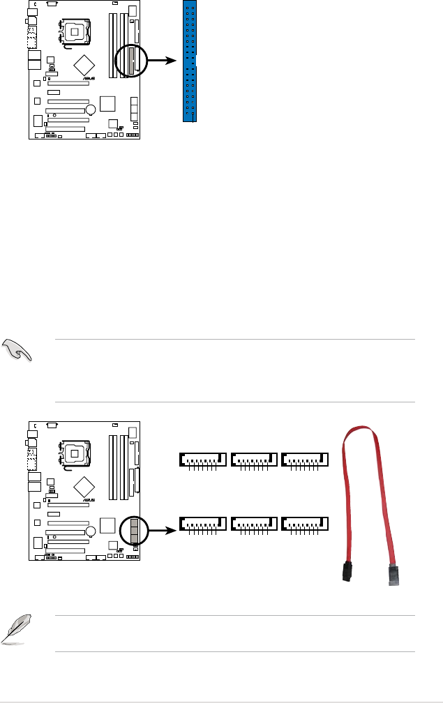
3. Serial ATA connectors (7-pin SATA1, SATA2, SATA3, SATA4, SATA5,
SATA6)
These connectors are for the Serial ATA signal cables for Serial ATA hard disk
drives.
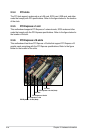
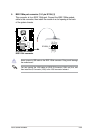
If you installed Serial ATA hard disk drives, you can create a RAID 0, RAID
1, RAID 0+1, RAID 5, or JBOD conguration with the onboard NVIDIA
®
MediaShield™ RAID controller.
The RAID function of these connectors is set to [Disabled] by default. If you
intend to create a Serial ATA RAID set using these connectors, enable the RAID
Enabled item under the Serial ATA Conguration sub-menu in the BIOS. See
section “4.5.3 Onboard Device Conguration” for details.
These connectors support Native Command Queuing (NCQ), Power
Management (PM) Implementation Algorithm, Hot Swap and smart setup.
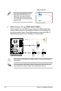
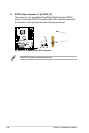
STRIKER EXTREME
®
STRIKER EXTREME IDE connector
NOTE: Orient the red markings
(usually zigzag) on the IDE
ribbon cable to PIN 1.
PRI_IDE
PIN 1
STRIKER EXTREME
®
STRIKER EXTREME SATA connectors
SATA1
GND
RSATA_TXP1
RSATA_TXN1
GND
RSATA_RXP1
RSATA_RXN1
GND
SATA2
GND
RSATA_TXP2
RSATA_TXN2
GND
RSATA_RXP2
RSATA_RXN2
GND
SATA3
GND
RSATA_TXP3
RSATA_TXN3
GND
RSATA_RXP3
RSATA_RXN3
GND
SATA4
GND
RSATA_TXP4
RSATA_TXN4
GND
RSATA_RXP4
RSATA_RXN4
GND
SATA5
GND
RSATA_TXP5
RSATA_TXN5
GND
RSATA_RXP5
RSATA_RXN5
GND
SATA6
GND
RSATA_TXP6
RSATA_TXN6
GND
RSATA_RXP6
RSATA_RXN6
GND