


52
Chapter 4: Motherboard info
4.4 Connectors
This section describes and illustrates the connectors on the motherboard.
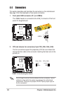
See page 19 for the description of rear panel connectors.
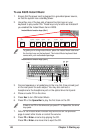
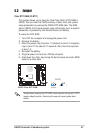
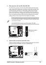
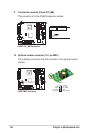
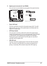
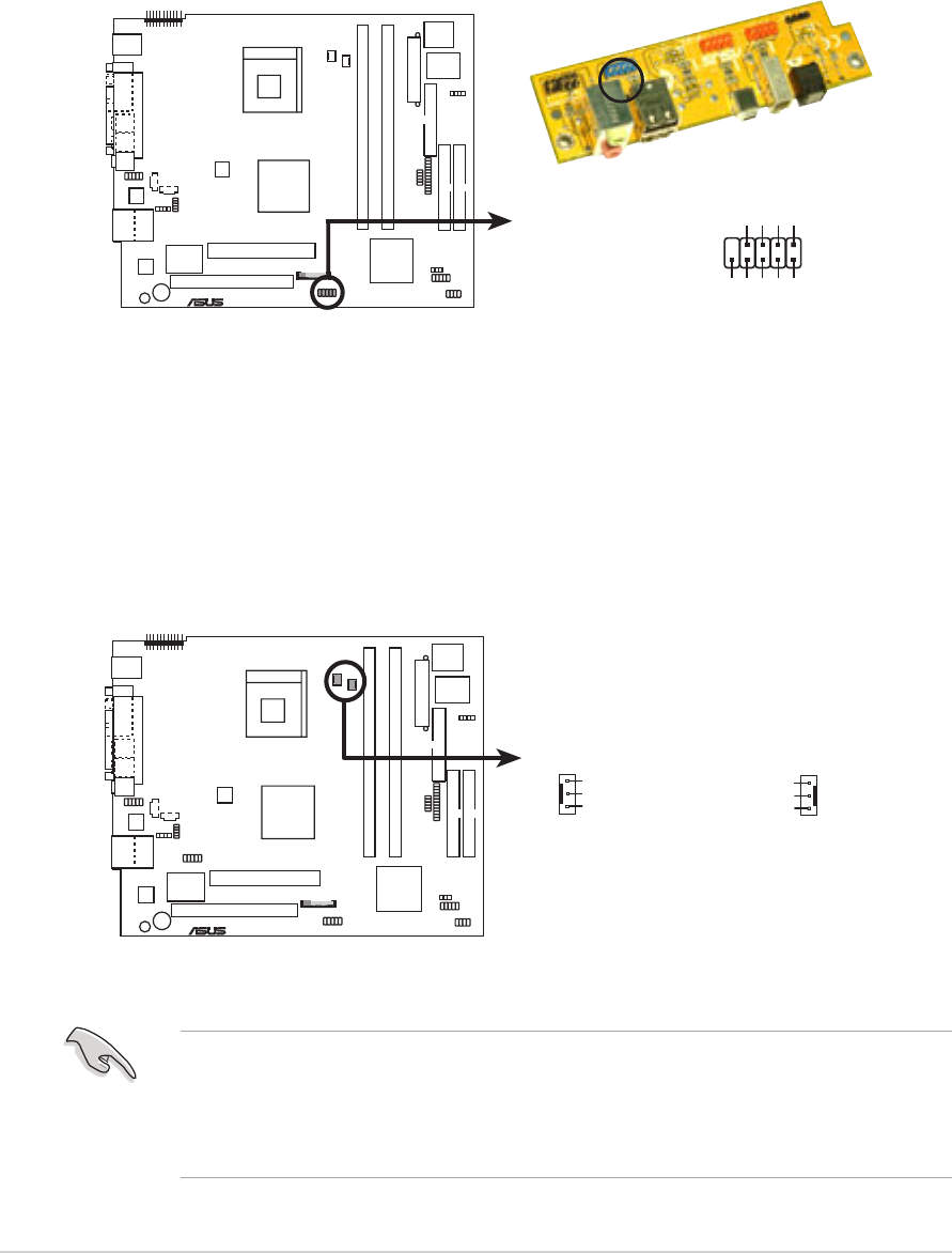
1. Front panel USB connector (10-1 pin USB56)
The USB56 header is connected to the USB_2 connector of the front
panel I/O daughterboard.
P4R8T
®
P4R8T USB Port
USB56
15
610
GND
USBP3+
USBP3-
USB Power
NC
GND
USBP2+
USBP2-
USB Power
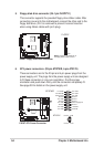
2. CPU and chassis fan connectors (3-pin CPU_FAN, CHA_FAN)
The fan connectors support the proprietary CPU fan and chassis fan.
Connect the fan cable to the connector matching the black wire to the
ground pin.
Do not forget to connect the fan cables to the fan connectors. Lack of
sufficient air flow within the system may damage the motherboard
components. These are not jumpers! DO NOT place jumper caps on
the fan connectors!
P4R8T
®
P4R8T 12-Volt Cooling Fan Power
CHA_FAN
GND
Rotation
+12V
GND
Rotation
+12V
CPU_FAN