


38 ASUS CUV4X-C User’s Manual
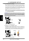
3. HARDWARE SETUP
Connectors
3. H/W SETUP
®
CUV4X-C
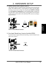
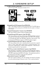
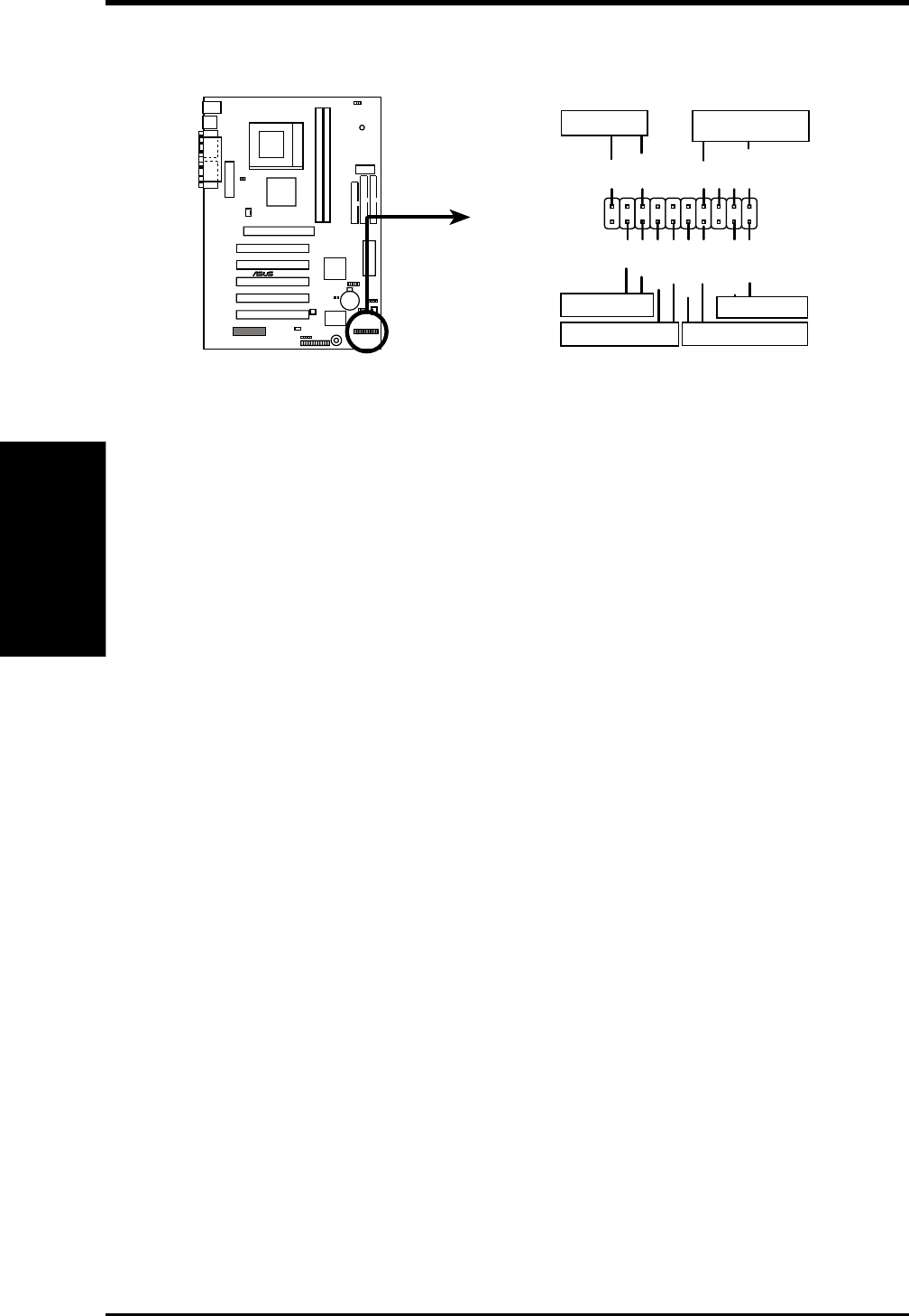
CUV4X-C System Panel Connectors
*
Requires an ATX power supply.
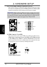
PLED
Ground
MLED
PWR_SW
+5 V
+5V
SPKR
Ground
+5 V
ExtSMI#
ResetCon
Ground
Ground
Reset SW
Power LED
ATX Power Switch*
Message LED
SMI Lead
Speaker
Connector
Ground
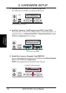
13) Panel Connector (20-pin SMB)
The following PANEL illustration is for items 14-19.
14) System Power LED Connector(3-1 pin PWR.LED)
This 3-1 pin connector connects to the system power LED. The LED lights up
when you turn on the system power, and blinks when the system is in sleep or
soft-off mode.
15) System Warning Speaker Connector (4-pin SPEAKER)
This 4-pin connector connects to the case-mounted speaker.
16) System Message LED Connector (2-pin MSG.LED)
This 2-pin connector is for the system message LED that indicates receipt of
messages from a fax/modem. The normal status for this LED is ON, when there
is no incoming data signal. The LED blinks when there is data received. The
system message LED feature requires an ACPI OS and driver support.
17) System Management Interrupt Connector (2-pin SMI)
This 2-pin connector allows you to manually place the system into a suspend
mode, or “Green” mode, where system activity is instantly decreased to save
power and to expand the life of certain system components. Attach the case-
mounted suspend switch this 2-pin connector.
18) ATX Power Switch / Soft-Off Switch Connector (2-pin PWR.SW)
The system power is controlled by a momentary switch attached to this connector.
Pressing the button switches the system between ON and SLEEP, or ON and
SOFT OFF, depending on the BIOS or OS settings. Pressing the button while in
the ON mode for more than 4 seconds turns the system off.
19) Reset Switch Connector (2-pin RESET)
This 2-pin connector connects to the case-mounted reset switch for rebooting
the system without turning off the power switch. This is a preferred method