


INTRODUCTION
CE-I
10/CE-120
INTRODUCTION
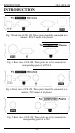
Fig. 2 Front
view
of CE-110. These ports should be connected to a
monitor, PC/AT mouse
&
keyboard.
Fig. 3 Rear view of CE-100. These ports are to be connected to
corresponding ports of a PC/AT.
Fig. 4 Front view of CE-120. These ports should be connected to a
monitor,
PS/2
mouse
&
keyboard.
L
t\
c’r”“‘“~;y(
m
6
;
Fig. 5 Rear view of CE-120. These ports are to be connected to
corresponding ports of a
PS/2.
-2-