


22
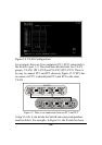
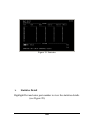
Figure 14. VLAN Configuration
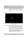
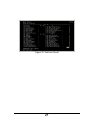
For example, there are five computers (PC1~PC5) connected to
the Switch’s port 1~5. They had been divided into two VLAN
groups: VLAN1 (PC1~PC4) and VLAN2 (PC2~PC5). There is
no way to connect PC1 and PC5 shown as Figure 15. If PC1 has
to connect to PC5, it should joint PC1 and PC5 in the same
VLAN.
1
2
3
4
VLAN1
5
2
3
4
VLAN2
X
Figure 15. There is no connection between PC1 and PC5
Using VLAN, it can divide the Switch into many independent
small switches. For example, in Figure 16, the Switch has been