OWNER'S MANUAL
Specifications are subject to change without notice
www.AtlasSound.com
1601 JACK MCKAY BOULEVARD ENNIS, TEXAS 75119 U.S.A. • TELEPHONE: (800) 876-3333 • FAX: (800) 765-3435
© 2007 ATLAS SOUND LP Printed in U.S.A. ATS002915 RevA 9/07 5
AA-PPRC
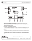
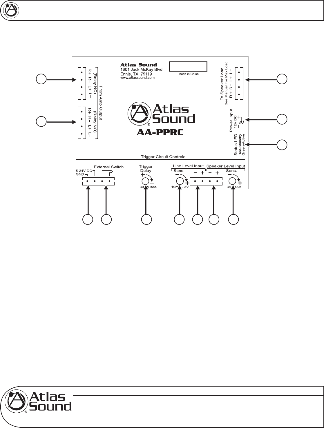
3.0 CONNECTION AND ADJUSTMENT IDENTIFICATION
1
2
12
11
10
3 4 5 6 7 8 9
1. Amplifier Input - Normally Closed Relay Contacts (NC)
Connect an amplifier power output to this input if you need the amplifier load to be disconnected when the trigger
circuit is activated. Note: “NC” stands for Normally Closed relay contacts, thus meaning it WILL pass signal thru to the
relay output contacts without power or circuit activation. Two amplifiers channels can be switch simultaneously but is
not required to use both inputs for operation.
2. Amplifier Input - Normally Open Relay Contacts (NO)
Connect an amplifier power output to this input if you need the amplifier load to be connected when the trigger circuit
is activated. Note: “NO” stands for Normally Open relay contacts, thus meaning it will NOT pass signal thru to the relay
output contacts without power or circuit activation. Two amplifiers channels can be switch simultaneously but is not
required to use both inputs for operation.
3. DC Trigger
This input allows the units trigger circuitry to be activated by supplying an external DC voltage to this input. The voltage
range is rated from 3V to 24V DC. Polarity does not matter.
4. External Switch Trigger
This input allows the units trigger circuitry to activate by an external contact closure. To activate, short these two points
together.


