


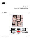

Using the ATAVRAUTO200
2-6 ATAVRAUTO200 User Guide
7698A–AUTO–01/07
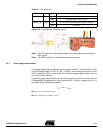
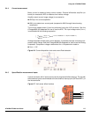
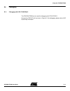
Figure 2-4. Power supply measurement through ADC1
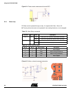
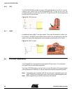
2.4.3 Motor relay
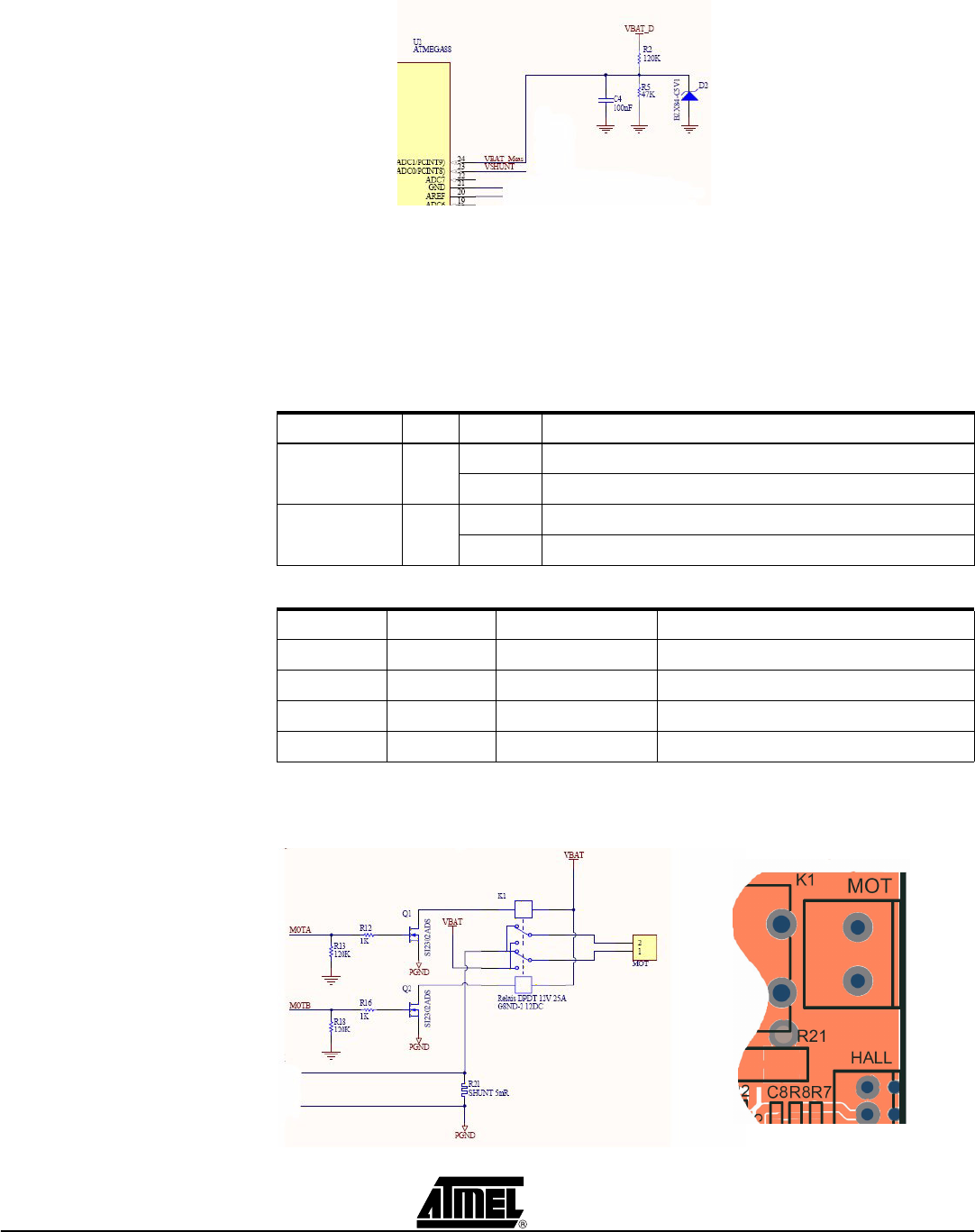
DC Motor can be operated through a relay. It is supplied with Vbat, -Vbat or 0V.
The relay allows the motor to be operated in two rotating directions, or to be stopped.
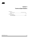
Table 2-2. Motor Relay commands
Figure 2-5. Motor on board command schematics
Function Port State Description
Mot_A PB1 Low/ Relay coil1 OFF (Normaly closed switch activated)
High Relay coil1 ON (Normaly opened switch activated)
Mot_B PB2 Low Relay coil2 OFF (Normaly closed switch activated)
High Relay coil2 ON (Normaly opened switch activated)
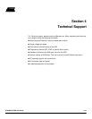
Table 2-3. Logical command table
Mot_A Mot_B Motor Supply Description
L L 0V Motor stopped
L H -Vbat Motor running (Direction B)
H L +Vbat Motor running (DirectionA)
H H 0V Motor stopped