


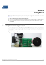

Description of the Application Board System
3-2 RFID Application Kit ATAK2270 User Manual
4871E–RFID–04/08
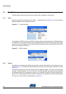
3.3.1 Frequency Tuning Mode Selection
The reader interface has a built-in frequency tuning feature. By the host software, the resonant fre-
quency of the LC antenna circuit can be switched in four steps. Therefore the board is equipped with two
stages of high-voltage transistor switches to tune the resonator via switched capacitors.
In default setting Tuning Mode is activated, allowing the adjusting of antenna frequency by host menu.
The binary control of the two tuning stages enables the selection of one out of four frequency states.
According to the menu definition the frequency steps are designated as follows:
High Frequency 134.2 kHz (acc. ISO11784/85)
Semi High Frequency 130 kHz
Semi Low Frequency 125 kHz
Low Frequency 121 kHz
In disabled mode, the interface operates with the fixed frequency adjusted typically to 125 kHz.
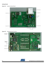
The currently selected frequency stage is displayed on the application board by the red LEDs Tune 1
and Tune 2 (shown in
Figure 2-2, see Table 5-1 for interpretation).
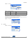
3.3.2 RF Field Control
The status of the RF field controlled by the microcontroller is indicated by the yellow LED RF on.
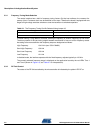
Table 3-1. The Frequency Tuning Can Be Selected Using Jumper J3
Tuning Mode Jumper J3 Position
Disabled 1-2
Enabled 2-3