


ATAVRAUTOEK1 Getting Started
ATAVRAUTOEK1 User Guide 1-2
7700A–AUTO–06/07
1.2 Overview
The ATAVRAUTOEK1 evaluation kit has been designed to give designers an easy and
fast way to develop automotive applications. The evaluation kit is shipped with a board
used as a vehicle network analyser (ATAVRAUTO102), a gateway between one LIN net-
work to one CAN network (ATAVRAUTO100), a DC motor control board
(ATAVRAUTO200) and a joystick board (ATAVRAUTO300).
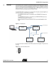
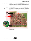
The ATAVRAUTOEK1 evaluation kit is shipped with all boards connected together on
the PCB (as describe in the following schematic):
– The ATAVRAUTO300 board is connected to the ATAVRAUTO102 board via
the LIN0.
– The ATAVRAUTO100 board is connected to the ATAVRAUTO200 and to the
ATAVRAUTO102 boards via the LIN1.
– Boards ATAVRAUTO100 and ATAVRAUTO102 are connected together via the
CAN.
Figure 1-1. Evaluation kit
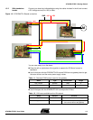
An 10-pins connector is available on the PCB to access internal signals. The pinout is as
following:
Figure 1-2. 10-pins connector pinout
Analyser
ATAVRAUTO102
ATAVRAUTO100
ATAVRAUTO200
ATAVRAUTO300
LIN to CAN
DC Motor
Joystick board
gateway borad
control board
LIN0
LIN1
CAN
USB
to any others LIN nodes
to any others CAN nodes
to any others LIN nodes
1
2
GND
VBat
LIN0
LIN1
CANHCANL
MOTA
MOTB
HALLA
HALLB