


AVR2016
5
8117D-AVR-04/08
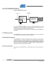
3.5 Speaker
An 8 speaker is provided. The ATmega3290P controls all audio. The signal source
is the TIMER1’s PWM output and the signal is shaped via a low-pass filter and
amplified by a Class-D amplifier. Pulling PORTE7 low activates the active filter and
providing a PWM signal on PORTB5 activates the amplifier.
3.6 Microphone
The AVRRAVEN’s microphone is connected to the ATmega3290P ADC channel 0.
The signal is amplified and low-pass filtered. Pulling PORTE7 low activates the
microphone circuit.
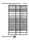
3.7 Serial Dataflash®
A 16-Mbits Atmel Serial Dataflash (AT45DB161D) is connected to the
ATmega3290P’s Serial Peripheral Interface (SPI). This storage is used for safe
firmware images, sounds and general-purpose parameters. See the firmware
documentation for an overview of occupied sectors, and those available to the end
user. Even with a couple of safe firmware images for the two microcontrollers there is
plenty space left for the end user. Please note that the serial Dataflash will operate
properly when the voltage is above 2.5 Volts while the rest of the design will operate
down to 1.8Volts
3.8 Serial EEPROM
A 2-Kbits Atmel Serial EEPROM (AT24C02B) is connected to the ATmega1284P’s
two-wire interface (TWI). This storage is write protected by hardware and can only be
read. The storage contains important configuration and calibration data that should
not be unintentionally overwritten. Information such as a unique EUI 64-bit address
can be found her-in. A rich set of access functions and the parameter map is given in
the RZRAVEN firmware documentation.
3.9 Real Time Clock
Separate 32768 Hz clock crystals are connected to the ATmega3290P’s and the
ATmega1284P’s asynchronous timer interfaces. This allows an application to
implement a real time clock (RTC) to keep track of time when sleep modes are used
to reduce the power consumption. This is especially important for battery-operated
nodes.
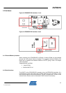
3.10 NTC
A NTC is connected to the ATmega3290P’s Analog to Digital Converter (ADC)
channel 4. This NTC can be used to measure the temperature in the surroundings of
the AVRRAVEN. The NTC can be found below the joystick, close to J401. The JTAG
interface must be disabled when using the temperature sensor. When running the
AVRRAVEN from an external power source the onboard voltage regulator may heat
the temperature sensor giving faulty reading. To avoid this the sensor NTC may be
soldered off and relocated using short wires. If a higher level of accuracy is required
the users may also calibrate the sensor by adjusting the temperature lookup table in
firmware.