


Page 10 AXIS P1355/P1357 Installation Guide
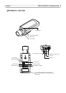
Unit connectors
Network connector - RJ-45 Ethernet connector. Supports Power over Ethernet. Using shielded
cables is recommended.
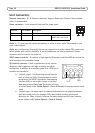
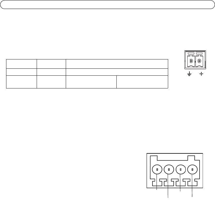
Power connector - 2-pin connector block used for power input.
Audio in - 3.5 mm input for a mono microphone, or a line-in mono signal (left channel is used
from a stereo signal).
Audio out - Audio output (line level) that can be connected to a public address (PA) system or an
active speaker with a built-in amplifier. A pair of headphones can also be attached. A stereo
connector must be used for the audio out.
SDHC memory card slot - A standard or high capacity SD memory card (microSD) can be used for
local recording with removable storage.
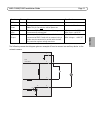
I/O terminal connector - Used in applications for e.g. motion
detection, event triggering, time lapse recording and alarm
notifications. In addition to an auxiliary power and a GND pin, it
provides the interface to:
• 1 digital output – For connecting external devices
such as relays and LEDs. Connected devices can be
activated by the VAPIX® Application Programming
Interface (API), by the output buttons on the Live
View page or by an Event Type. The output will show
as active (shown under System Options > Ports & Devices) if the alarm device is acti-
vated.
• 1 digital input – An alarm input for connecting devices that can toggle between an
open and closed circuit, for example: PIRs, door/window contacts, glass break
detectors, etc. When a signal is received the state changes and the input becomes
active (shown under System Options > Ports & Devices).
Function Pin number Description
GND 1 Ground
DC Power 2 Power input 8-20 V DC AXIS P1355: max 7.1 W
AXIS P1357: max 7.9 W
1
2
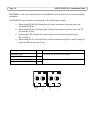
Pin 3
Pin 4
Pin 2
Pin 1