


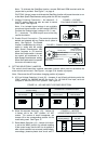

IX. DIAGNOSTIC LEDs
The motor control is designed with LEDs mounted on the front cover to display the control’s
operational status.
A. Power On (ON) – Indicates the presence of bus voltage.
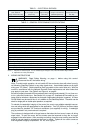
B. Status (STATUS) – The Status LED is a tricolor LED that provides indication of the con-
trol’s operational status including installation problems such as incorrect input voltage,
overvoltage, undervoltage and control miswiring. It also provides a "normal" indication if
all control and microcontroller operating parameters are proper. See Table 5 on page 12.
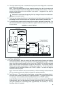
X. OPTIONALACCESSORIES
Complete instructions and connection diagrams are supplied with all accessories to facilitate
installation.
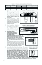
A. Forward-Stop-Reverse Switch (ID5FSR-1) – Provides motor reversing and stop func-
tions. Mounts on the enclosure cover and is supplied with a switch seal to maintain water-
tight integrity.
B. Signal Isolator/Run Relay (ID5SI-2) – Provides isolation between a non-isolated signal
voltage source and the drive and contains a Run Relay which can be used to turn on or
off equipment or to signal a warning if the control is put into the Stop Mode or a fault has
occured.
C. Auto/Manual Switch (ID5AMS-1) – When used with the ID5SI-2, it either selects an iso-
lated signal from the ID5SI-2 or the Main Speed Potentiometer. Mounts on the enclosure
cover and is supplied with a switch seal to maintain watertight integrity.
13