


Documentation Number 232CCxx4502 33
B&B Electronics Mfg Co – 707 Dayton Rd - PO Box 1040 - Ottawa IL 61350 - Ph 815-433-5100 - Fax 815-433-5104
B&B Electronics Ltd – Westlink Comm. Pk – Oranmore, Galway, Ireland – Ph +353 91-792444 – Fax +353 91-792445
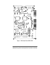
When setting the address (via the dipswitch) use the silkscreen
on the printed circuit board. This silkscreen shows a “1” and a “0” --
referring to the “on and “off” states that each switch is set to. Switch
S1 configures port one (labeled J1) and, on two port cards, switch
S2 configures port two (labeled J2). Least significant bit (LSB) and
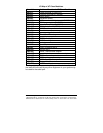
most significant bit (MSB) are labeled on the card. Table 1 shows
the numerical weight and electrical connection of each switch
position. Refer to Table 2 for COM Port addresses. Table 3 shows
frequently unused port addresses for applications when COM Port
addresses 1-4 are already used.
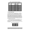
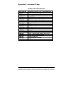
To install the 232CC card as COM1, 2, 3, or 4, follow the switch
settings shown in Table 2. To install at another address, follow the
switch settings shown in Table 3.
Table 2. Standard Port Addresses
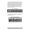
Table 1. Address Switches
SwitchPosition7654321
Bus Connection SA9 SA8 SA7 SA6 SA5 SA4 SA3
Decimal Weight 512 256 128 64 32 16 8
Hex Weight 200 100 80 40 20 10 8
Base Hex
Address
Binary
Equivalent
Switch Settings
MSB LSB
7654321
COM1 3F8 1111111000 1111111
COM2 2F8 1011111000 1011111
COM3 3E8 1111101000 1111101
COM4 2E8 1011101000 1011101