


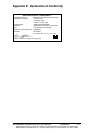

Documentation Number 232PCIXX4502 Manual Appendix B B -1
B&BElectronicsMfgCo–707DaytonRd-POBox1040-OttawaIL61350-Ph815-433-5100-Fax815-433-5104
B&BElectronicsLtd–WestlinkComm.Pk.–Oranmore,Galway,Ireland–Ph+35391-792444–Fax+35391-792445
Appendix B: RS-232 Pinouts
Table 1: RS-232 Pinouts (DTE)
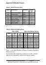
Table 2: Reference Cabling Table
DB9 to DB25 DB9 to Null Modem Cabling
Name DB9
Pin
To
DB25
DB9
Pin
DB9 Null DB25 Null
DCD 1 8 1 **
RD 2 3 2 3 2
TD 3 2 3 2 3
DTR 4 20 4 6 6
GND 5 7 55 7
DSR 6 6 6 4 20
RTS 7 4 7 85
CTS 8 5 8 7 4
RI 9 22 9 --
NOTE: In null cables, the DCD connection is usually connected to
DSR at each end.
2 Channel RS-232 Handshaking loopback for Tx & Rx: Connect
DB9 pins #7 & #8 together, and pins #4   together.
Name Description Direction DB9M
Pin
DCD Data Carrier Detect Input 1
RD Receive Data Input 2
TD Transmit Data Output 3
DTR Data Terminal Ready Output 4
GND Signal Ground ----- 5
DSR Data Set Ready Input 6
RTS Request to Send Output 7
CTS Clear to Send Input 8
RI Ring Indicator Input 9