


232XS5-1005 Manual 13
B&B Electronics Mfg Co Inc – 707 Dayton Rd - PO Box 1040 - Ottawa IL 61350 - Ph 815-433-5100 - Fax 815-433-5104
B&B Electronics Ltd – Westlink Commercial Park – Oranmore, Galway, Ireland – Ph +353 91-792444 – Fax +353 91-792445
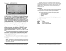
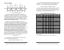
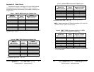
Expansion Mode
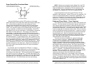
The number of serial ports on the 232XS5 can easily be
expanded to a maximum of seventeen ports. Up to four 232XS5
units may be cascaded in expander mode. Each unit address adds
four additional serial ports to the five on unit address “A”. Port C is
used as the expansion port that connects to the follow-on master-
port for switch units addressed “B” thru “D”. Expansion Switch unit
address “A” is the last Switch in the chain.
Expander mode is selected when jumper “JP6-B” is OFF
(removed.) In Expander mode, the 232XS5 is constantly looking for
a four character preamble code by monitoring the data that is being
received on the master port from the host device. The 232XS5
requires a four character preamble code to turn on and off a port.
The first character must be the ASCII escape character (decimal
27). The second character is user programmable by setting
dipswitch “SW2”. “SW2” comes from the factory programmed to the
ASCII character STX (decimal 2). The third character is the
Expansion Switch Unit Address character “A” through “D”. The
fourth character should be the ASCII upper case letters "A", "B", "C",
"D" or “E” (decimal 65, 66, 67, 68 or 69 respectively) to select those
ports. To turn off the selected port the third character should be the
ASCII EOT character (decimal 4). For instance, to turn on port B of
Expansion Switch unit address C, you would send:
ESC STX C B
If you were writing a program in BASIC to control the Smart
Switch you would form a string like this:
SWB$ = CHR$(27) + CHR$(2) + "C" + ”B”
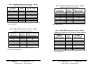
Master
Port
Expansion
Port
17-Port Cascaded Expansion Mode
Address D
C
C
Address C
Slave
Port
B
Slave
Port
A
Slave
Port
A
Address B
Slave
Port
Slave
Port
A
B
Slave
Port
B
C
Slave
Port
DE
Slave
Port
E
Slave
Port
Expansion
Port
E
Slave
Port
D
Slave
Port
Expansion
Port
Slave
Port
D
C
Slave
Port
Slave
Port
Slave
Port
Address A
AB
ED
Slave
Port
Slave
Port
232XS5-1005 Manual
B&B Electronics Mfg Co Inc – 707 Dayton Rd - PO Box 1040 - Ottawa IL 61350 - Ph 815-433-5100 - Fax 815-433-5104
B&B Electronics Ltd – Westlink Commercial Park – Oranmore, Galway, Ireland – Ph +353 91-792444 – Fax +353 91-792445
14
You could then send SWB$ to select port B of Expansion switch
unit address “C”. Similar strings could be used for turning on the
other ports. To turn off the ports the string might look like this:
TOFF$ = CHR$(27) + CHR$(2) + CHR$(4)
When you are done with a port you can either select a new one
directly or turn off the selected port and then turn on the next one.
For information on preventing command codes from being received
by slave devices, refer to the Enhanced Mode section.
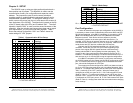
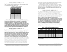
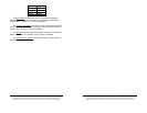
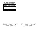
Table 9 - 232XS5 Expander Mode Commands
* X represents the programmable character set by dipswitch SW2
** NU = Not Used
***Port C is used as the expansion port for unit addresses B thru D.
Command Characters
Function 1st 2nd 3rd 4th Comments
Select Port A ESC X* “A” “A” Address A
Select Port B ESC X* “A” “B” Address A
Select Port C ESC X* “A” “C”*** Address A
Select Port D ESC X* “A” “D” Address A
Select Port E ESC X* “A” “E” Address A
Select Port A ESC X* “B” “A” Address B
Select Port B ESC X* “B” “B” Address B
Select Port D ESC X* “B” “D” Address B
Select Port E ESC X* “B” “E” Address B
Select Port A ESC X* “C” “A” Address C
Select Port B ESC X* “C” “B” Address C
Select Port D ESC X* “C” “D” Address C
Select Port E ESC X* “C” “E” Address C
Select Port A ESC X* “D” “A” Address D
Select Port B ESC X* “D” “B” Address D
Select Port D ESC X* “D” “D” Address D
Select Port E ESC X* “D” “E” Address D
Deselect Port ESC X* EOT NU** Switching Command
Set Timer Value ESC X* “T” “0”-”9” Enhanced Mode
Set Timer Mode ESC X* “M” “0”,”1” Enhanced Mode