


B-2 Appendix B 232XS53800 Manual
B&B Electronics -- PO Box 1040 -- Ottawa, IL 61350
PH (815) 433-5100 -- FAX (815) 433-5109
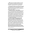
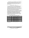
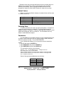
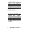
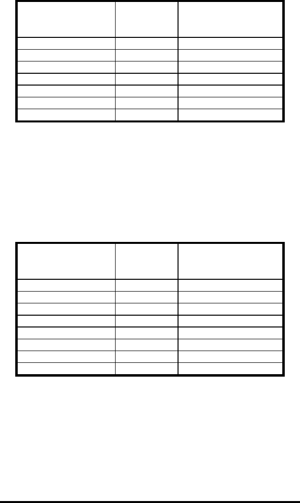
Chart 3. Modem DB25 Connector to Master Port
* Pins are tied together inside the 232XS5, they are not
connected to ports A, B, C, D, or E.
NOTE: When connecting a DTE device to ports A, B, C, D or E of
the smart switch, refer to Charts 8 and 9.
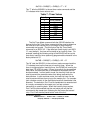
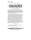
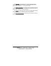
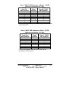
Chart 4. IBM PC DB25 Connector to Ports A - E (DTE)
Master port configured as a DCE port.
* Pins are tied together inside the 232XS5, they are not connected
to the master port.
Async Modem
Serial Port
DB25 Connector
Signal
Direction
232XS5
Master Port (DTE)
DB9 Connector
2 <----------- 3
3 -----------> 2
4 <----------- 6
5 -----------> 4
7 <---------> 5*
8 -----------> 8
20 <----------- 7
IBM PC
Serial Port
DB25 Connector
Signal
Direction
232XS5
Ports A - E (DTE)
DB9 Connector
2 -----------> 2
3 <----------- 3
4 -----------> 8
5 <---------- 7
6 <---------- 6
7 <---------> 5
8 <----------- 4*
20 -----------> 4*