


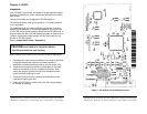

Documentation Number 3PCIOSD1x-3903m Manual Chapter 2 7
B&B Electronics Mfg Co – 707 Dayton Rd - PO Box 1040 - Ottawa IL 61350 - Ph 815-433-5100 - Fax 815-433-5104
B&B Electronics Ltd – Westlink Comm. Pk. – Oranmore, Galway, Ireland – Ph +353 91-792444 – Fax +353 91-792445
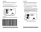
RS-232 Mode
To configure the port for RS-232 mode, 5 jumpers must be
set/checked. The following settings will configure the port as RS-
232:
1. Set four jumpers of JP2 (A-D) to the "232" (left) position.
2. Set JP1 to the "RTS(232)" (right) position.
The remaining jumpers, JP4, are unused in the RS-232 mode and
may be in either position. Figure 2 shows the jumper configuration to
set the port for RS-232 mode with *1 clock enabled.
Figure 2. RS-232 Mode Jumper Settings
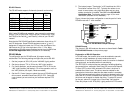
RS-232 Pinouts
The DB-25 male connector on the 3PCIOSD1x cards is configured
as standard DTE RS-232 serial port. Table 1 lists pin numbers and
descriptors.
Table 1: RS-232 Pinouts
Name Description Direction DB25M Pin
Shield Shield ------ 1
TD Transmit Data Output 2
RD Receive Data Input 3
RTS Request to Send Output 4
CTS Clear to Send Input 5
DSR Data Set Ready Input 6
GND Signal Ground ------ 7
DCD Data Carrier Detect Input 8
DTR Data Terminal Ready Output 20
JP2
JP4
JP1
JP3
CONTROL
A 232
D 232
B 232
C 232
422/ 485
MODES
422/ 485
422/ 485
422/ 485
TX 422
RX 422
485
485
IN OUT
*4
*1
SD
RTS( 2 32)
TERMINAT I ON
CLOCK
8 Chapter 2 Documentation Number 3PCIOSD1x-3903m Manual
B&B Electronics Mfg Co – 707 Dayton Rd - PO Box 1040 - Ottawa IL 61350 - Ph 815-433-5100 - Fax 815-433-5104
B&B Electronics Ltd – Westlink Comm. Pk. – Oranmore, Galway, Ireland – Ph +353 91-792444 – Fax +353 91-792445
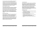
RS-422 Mode
To configure the port for RS-422 mode, 7 jumpers must be
set/checked. The following settings configure the port as RS-422:
1. Set the four jumpers of JP2 (A-D) to the "422/485" (right)
position.
2. Set the top jumper "TX" of JP4 to the “422” (left) position.
3. Set the second jumper "RX" of JP4 to the “422” (left) position.
4. The JP1 Control (SD/RTS) jumper is unused in the RS-422
mode and may be in either position.
5. The bottom jumper "Termination" of JP4 switches the 120Ω
receiver termination resistor IN or OUT. Typically this resistor is
not used. In some cases using high baud rates and very long
cables, termination is needed. See B&B Electronics’ free RS-
422/485 Application Note (available on our websites),
Termination section, page 16, for more information. Figure 3
shows the jumper configuration to set the port for RS-422 mode
with *1 clock enabled.
Figure 3. RS-422 Mode Jumper Settings
JP2
JP4
JP1
JP3
CONTROL
A 232
D 232
B 232
C 232
422/ 485
MODES
422/ 485
422/ 485
422/ 485
TX 422
RX 422
485
485
IN
OUT
*4
*1
SD
RTS( 232)
CLOCK
TERMINATI ON