


Documentation Number 232BSS4-2907m 21
&B Electronics Mfg Co Inc – 707 Dayton Rd - PO Box 1040 - Ottawa IL 61350 - Ph 815-433-5100 - Fax 815-433-5104 – www.bb-elec.com
B&B Electronics – Westlink Commercial Park – Oranmore, Galway, Ireland – Ph +353 91-792444 – Fax +353 91-792445 – www.bb-europe.com
Chapter 3: PORT CONNECTIONS
DTE/DCE Explanation
In order to determine the proper port connections to the 232BSS4, it is
necessary to have a basic understanding of the terms DTE and DCE. RS-
232 was designed, using DB-25 connectors, for connecting a DTE (Data
Terminal Equipment) device to a DCE (Data Communication Equipment)
device. Each device will have inputs on pins that correspond to outputs on
the same pins of the other device. For example, a DTE device will transmit
data out on pin 2 (on a DB-25) and a DCE device will receive data in on
pin 2 (on a DB-25). IBM PCs and serial printers are DTE devices, modems
are DCE devices.
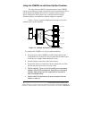
Originally the RS-232 standard specified only a 25 pin D-sub
connector. Since then, the use of a 9 pin D-Sub supporting only a portion of
the original RS-232 signals has been used extensively, starting with the
IBM PC and migrating into other peripherals. The pinouts for this 9 pin
connector have since become the EIA/TIA 574 standard. This standard
specifies a DTE device that transmits on pin 3 and receives on pin 2, with
the DCE having the opposite configuration.
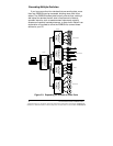
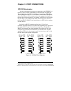
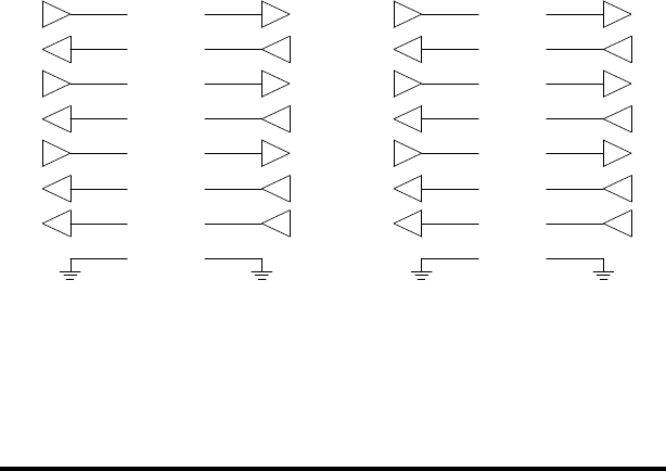
25 Pin DTE
2 (TD)
4 (RTS)
3 (RD)
5 (CTS)
20 (DTR)
6 (DSR)
8 (DCD)
7 (GND)
25 Pin DCE
2 (TD)
4 (RTS)
3 (RD)
5 (CTS)
20 (DTR)
6 (DSR)
8 (DCD)
7 (GND)
9 Pin DCE
3 (TD)
7 (RTS)
2 (RD)
8 (CTS)
4 (DTR)
6 (DSR)
1 (DCD)
5 (GND)
T
T
T
T
T
T
TT
T
T
T
R
R
R
R
R
R
RR
R
R
T = RS-232 Transmitter R = RS-232 Receiver
DEVICE LINE DEVICELINE
9 Pin DTE
3 (TD)
7 (RTS)
2 (RD)
8 (CTS)
4 (DTR)
6 (DSR)
1 (DCD)
5 (GND)
T
T
T
R
R
R
R
DEVICE LINE DEVICELINE
Figure 3.1. DTE/DCE Port Diagrams