


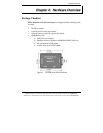


Hardware Overview
6 Manual Documentation Number: ES1A -2907m pn7041-rev002
B&B Electronics Mfg Co Inc – 707 Dayton Rd - PO Box 1040 - Ottawa IL 61350 - Ph 815-433-5100 - Fax 815-433-5104 – www.bb-elec.com
B&B Electronics Ltd – Westlink Commercial Park – Oranmore, Galway, Ireland – Ph +353 91-792444 – Fax +353 91-792445 – www.bb-europe.com
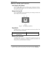
Indicators, Switches and Connectors
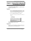
Link Integrity LED (Yellow)
When the yellow LED located on the Ethernet jack is illuminated it indicates
that a connection (link integrity) has been established between the converter
and a node on the network.
Network Activity LED
When the green LED located on the Ethernet jack is flashing it indicates that
data is being sent across the network.
Figure 3. LED Indicators on the ES1A
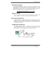
Reset Switch
The Reset switch is a recessed switch located on the side of the ES1A. The
Reset switch provides two functions:
Press and release within 10 seconds Resets the ES1A
Press and hold for more than 10 seconds
while powering up
Reloads factory default values
Ethernet Port Connector
The Ethernet Port connector is a standard RJ-45 receptacle that allows the
serial server to be connected to an Ethernet network. On the ES1A two
indicator LEDs are built into the RJ-45 connector.