


RS-485 Connections
Manual Documentation Number: ESP904-0504 Appendix C 65
B&B Electronics Mfg Co Inc – 707 Dayton Rd - PO Box 1040 - Ottawa IL 61350 - Ph 815-433-5100 - Fax 815-433-5104 – www.bb-elec.com
B&B Electronics Ltd – Westlink Commercial Park – Oranmore, Galway, Ireland – Ph +353 91-792444 – Fax +353 91-792445 – www.bb-europe.com
A
A
P
P
P
P
E
E
N
N
D
D
I
I
X
X
C
C
:
:
R
R
S
S
-
-
4
4
8
8
5
5
C
C
O
O
N
N
N
N
E
E
C
C
T
T
I
I
O
O
N
N
S
S
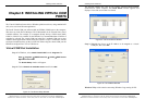
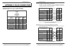
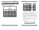
ESP904 DB-9 Pin-out in RS-485 Mode
RS-485
Signal Name
Direction RS-485 DB9M
Pin
Data B (+) In/Out DATA B (+) 3
Data A (−) In/Out DATA A (−) 4
Signal Ground --- GND 5
Figure 51. DB-9 Pin-out in RS-485 Mode
N
N
o
o
t
t
e
e
:
:
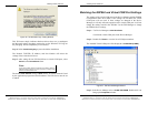
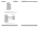
Some RS-485 devices are marked opposite the RS-485 standard, which
defines the Data B line as positive relative to Data A during a Mark state before
enabling the transmitter, and after transmitting before tri-stating. If an RS-485
device does not respond, try swapping the Data B and Data A lines.
Figure 52. 2-wire RS-485 Connection
RS-485 Connections
66 Appendix C Manual Documentation Number: ESP904-0504
B&B Electronics Mfg Co Inc – 707 Dayton Rd - PO Box 1040 - Ottawa IL 61350 - Ph 815-433-5100 - Fax 815-433-5104 – www.bb-elec.com
B&B Electronics Ltd – Westlink Commercial Park – Oranmore, Galway, Ireland – Ph +353 91-792444 – Fax +353 91-792445 – www.bb-europe.com
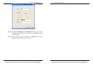
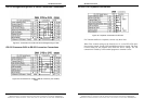
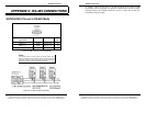
To connect 4-Wire RS-485 devices, the RS-422 Mode can be used provided
the ESP904 will be connected as a master in a single master system. If using
multiple masters, the ESP904 cannot be used, as it does not tri-state the
transmitter in RS-422 mode.