


Introduction
Documentation Number: ESR90xW-4905m Chapter 1 3
B&B Electronics Mfg Co Inc – 707 Dayton Rd - PO Box 1040 - Ottawa IL 61350 - Ph 815-433-5100 - Fax 815-433-5104 – www.bb-elec.com
B&B Electronics Ltd – Westlink Commercial Park – Oranmore, Galway, Ireland – Ph +353 91-792444 – Fax +353 91-792445 – www.bb-europe.com
Virtual COM Mode
Virtual COM Mode allows application programs to effectively extend their
COM ports across the network. Data sent to that port is redirected via the
network to a COM port on the serial server. Windows programs using
standard Windows API calls are able to interface to these virtual COM ports.
When a program on the PC opens the port, it communicates with the remote
serial device connected to one of the ports on the serial server.
After connection, the LAN is transparent to the program and serial device.
Applications are able to work just as if the serial device is connected directly
to a physical COM port on the computer. The virtual COM port software
converts the application’s data into IP packets, sends it across the network to
the serial server, which converts the IP packet back to serial data and sends
the data out a serial port located on the serial server.
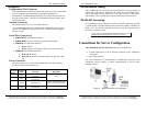
Serial Tunneling Mode
Serial Tunneling is also called paired mode. In this mode any two serial
devices that can communicate across the wireless link will be able to
communicate using two serial servers.
One server is configured as a TCP or UDP client and the other as a
TCP/UDP server. When setting up the server the remote IP address section
must contain the address of the client. This will allow the client’s IP address
to pass the IP address-filtering feature of the server. Conversely, the Remote
IP address of the client must contain the server’s IP address. Both
communication port numbers must be the same.
802.11 Wireless Networking Basics
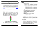
Vlinx ESR90xW wireless serial servers allow you to connect non-network-
enabled serial devices into a wireless network, giving you the capability to
gather more data and implement remote programming and management.
Serial devices no longer are limited to a physical connection to a PC. The
serial device can be connected to a Vlinx ESR90xW wireless serial server
anywhere within range of an 802.11g compatible wireless access point.
Communication occurs transparently using TCP/IP or UDP/IP over a
wireless link. This allows traditional Windows PC software access to serial
devices anywhere on the wireless network.
The enabling technology for Vlinx ESR90xW wireless serial servers is
based on the IEEE 802 standard. Some background on the standard follows.
Introduction
4 Chapter 1 Documentation Number: ESR90xW-4905m
B&B Electronics Mfg Co Inc – 707 Dayton Rd - PO Box 1040 - Ottawa IL 61350 - Ph 815-433-5100 - Fax 815-433-5104 – www.bb-elec.com
B&B Electronics Ltd – Westlink Commercial Park – Oranmore, Galway, Ireland – Ph +353 91-792444 – Fax +353 91-792445 – www.bb-europe.com
802.11 Wireless Networking
IEEE 802.11 is a set of standards that defines how multiple devices can
communicate on a wireless network. The standard has grown into a set of
several standards that define various features and functions. The 802.11g
standard defines the physical and data link layers for a wireless network
using the 2.4 GHz frequency band, a band that does not require licensing. As
a part of the IEEE family of standards, 802.11 WLANs are easily connected
to 802.3 (Ethernet) LANs. Higher layer LAN protocols, network operating
systems and internetworking protocols such as TCP/IP integrate seamlessly.
Under the IEEE 802.11 standard there can be two different types of devices
on the wireless network: stations and access points (AP). A station often is a
PC equipped with a wireless network adapter. An 802.11 access point is a
radio with an interface that allows connection to a wired LAN. Access points
run bridging software to facilitate the connection from wireless to wired
network. The access point becomes the base station for the WLAN. It
aggregates access to the wired network for multiple wireless stations. An
access point may be a standalone device or a card in a PC.
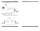
Wireless Network Configurations
The 802.11 standard defines two modes of operation: infrastructure mode
and ad hoc mode. Infrastructure mode makes use of one or more access
points connected to a wired LAN. Wireless stations communicate with access
points to gain access to each other and/or the LAN. In the Basic Service Set
(BSS) several stations communicate with one access point, which is
connected to a wired LAN. In the Extended Service Set (ESS) two or more
access points connect to the LAN creating a subnetwork.
In ad hoc mode, also called Independent Basic Service Set (IBSS), access
points are not used. Wireless stations communicate directly with each other
in a peer-to-peer fashion. This mode allows individual computers to set up a
network where wireless infrastructure does not exist.
Vlinx ESR90xW wireless serial servers can be configured to operate in
infrastructure mode only, ad hoc mode is not supported at this time. During
device configuration a wireless configuration wizard guides you through the
process of setting up the type of network, naming the network (specifying the
SSID, or service set identifier) and other parameters.