


Documentation Number 3PCISD4x-3903 Manual Chapter 2 9
B&B Electronics Mfg Co – 707 Dayton Rd - PO Box 1040 - Ottawa IL 61350 - Ph 815-433-5100 - Fax 815-433-5104
B&B Electronics Ltd – Westlink Comm. Pk. – Oranmore, Galway, Ireland – Ph +353 91-792444 – Fax +353 91-792445
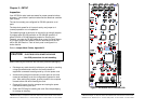
5. Set the fourth jumper of JP3 (D) to select the type of RS-485
transmit driver control, RTS or Send Data. Select SD control
unless you are sure your software requires RTS control.
6. The bottom jumper of JP3 (E) switches the 120Ω receiver
termination resistor in or out. Typically this resistor is not used.
In some cases using high baud rates and very long cables,
termination is needed. See our RS-422/485 Application Note
(available on our websites).
7. Configure each port as above using the table in Appendix B.
RS-485 Pinouts
The pinouts in RS-485 mode are the same as those listed in Table 8
for RS-422 mode.
Explanation of RS-485 Operation
In RS-485 mode, the transmit driver must be enabled to transmit,
and set to a high impedance (tri-state) mode at the end of
transmission. In two wire (half duplex) mode, the receiver is
disabled during transmit, and enabled when not transmitting.
The 3PCISD4 card provides two methods of enabling/disabling the
transmit driver: automatic Send Data (SD) control and Request To
Send (RTS) control. With automatic SD control, the transmit driver
is enabled when data is sent. The driver remains enabled for the
transmission time and ten data bits after data transfer is complete.
The SD circuit automatically adjusts its timing to the baud rate of the
data. With RTS control, software must assert the RTS line to enable
the driver and disassert to disable the driver. To select SD control
for Port 1, place the fourth jumper of JP3 (D) in the SD (right)
position. Place this jumper in the RTS (left) position for RTS control.
The receiver can also be enabled and disabled, a useful feature in
two-wire communications to prevent the transmitted data from
"echoing back" on its own receiver. The second jumper on JP3 (B)
determines the receiver mode. If the jumpers are placed in the 485
position, the "echo" is turned off. This is achieved by disabling the
receiver when the transmit driver is enabled. Placing this jumper in
the 422 position will hold the receiver enabled at all times.
Refer to the Jumper Mode Table in Appendix B for all ports. More
information on RS-485 communications can be found in our RS-
422/485 Application Note (available on our websites).
10 Chapter 2 Documentation Number 3PCISD4x-3903 Manual
B&B Electronics Mfg Co – 707 Dayton Rd - PO Box 1040 - Ottawa IL 61350 - Ph 815-433-5100 - Fax 815-433-5104
B&B Electronics Ltd – Westlink Comm. Pk. – Oranmore, Galway, Ireland – Ph +353 91-792444 – Fax +353 91-792445
RS-422 and RS-485 Termination
An 120Ω termination resistor has been provided for the RS-422/485
receivers. Note that termination should only be used in systems
with both high baud rates (>19200) and over several thousand feet
of cable. If a value other than 120Ω is desired, space for a through
hole resistor has been provided on the board adjacent to the surface
mount termination resistor. The termination resistors are labeled
RTAB, RTBB, RTCB and RTDB for ports 1, 2, 3 and 4 respectively.
See our RS-422/485 Application Note for more discussion on
termination (available on our websites).
4X Baud Rate Option
Baud rates higher than 115,200 are possible with the 3PCISD4x
card in RS-232, 422, or 485 mode. Jumper JP5 controls the clock
frequency supplied to the UARTs. By moving this jumper to the *4
(left) position, the clock frequency is increased from 1.8432 to
7.3728 MHz. This multiplies all UART baud rates by 4 times. For
example, if the software is set for 57.6 Kbaud, the actual baud rate
will be increased by a factor of four to 230.4 Kbaud. In many
systems, these higher baud rates can improve throughput
significantly. However, remember that baud rates and actual
throughput are only proportional if the system can keep up with the
communications, otherwise increasing the baud rate effectively only
increases the idle time between characters.
continued next page