


P#8506R2 ULINX 1&2 PORT_0712qsg
5
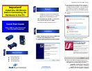
Dip Switch Setting
TDA(-)
TDB(-)
RDA(-)
RDB(-)
GND
USB
TO PC
RS-485
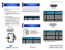
RS-232 and TTL Pinout (DB9 Male DTE)
PIN Signal Name
RS-232
Signals
TTL
Signals
1 DCD (Data Carrier Detect) Input Not Used
2 RD (Receive Data) Input Input
3 TD (Transmit Data) Output Output
4 DTR (DTE Ready) Output Not Used
5 SG (Signal Ground) Ground Ground
6 DSR (DCE Ready) Input Not Used
7 RTS (Request to Send) Output Output
8 CTS (Clear to Send) Input Input
9 RI (Ring Indicator) Input Not Used
NOTE: To remove drivers from a PC, there is an Uninstall
reference document on the CD ROM.
1. To verify the installation went correctly open the Windows
Device Manager
Scroll down to Ports,
Expand the ports by clicking on the plus sign (+), this
shows if the ports now exist on the PC.
If there are no exclamation points or other indicators of
a problem the ports should be installed correctly and
ready for use.
2. Verifying with a loopback test.
If the device is RS-232, loopback pins 2 and 3. If the
device is RS-422 or RS-485, loopback the TDA(-) to
RDA(-) and TDB(+) to RDB(+). Use the pin-out charts
for the location of each pin or terminal.
Using Hyper Terminal or similar program, connect to
the appropriate COM port. Set the desired baud rate.
Ensure Hyper Terminal local echo is OFF. (Note:
Hyper Terminal is not provided with Vista or 2003
Server)
Transmit data. If the same character string is returned,
the test is good.
4
Verifying Installation
Dip Switch Settings
Switch Off (left) On (right)
1 RS-422 RS-485
2 ECHO ON ECHO OFF
3 4-Wire 2-Wire
4 4-WIre 2-Wire
6
Pinouts
RS485 Pinout (Terminal Blocks)
Terminal
Position
RS-485, 4 Wire RS-485, 2 Wire
A Transmit TDA (-) Output Data A (-) Input / Output
B Transmit TDB (+) Output Data B (+) Input / Output
C Receive RDA (-) Input Data A (-) Input / Output
D Recieve RDB (+) Input Data B (+) Input / Output
E Ground Ground
Note: For models with selectable RS-422/485 configurations
Dip switches allow the module to be configured for two-wire or
four-wire, RS-422 or RS-485 modes. In two-wire mode the TDA (-)
and RDA (-) are tied together and so are TDB (+) and RDB (+),
making multi-dropping this converter into an existing network easy.
RS-232
RS-485 Pinout (DB9 Female)
Pin RS-485, 4 Wire RS-485, 2 Wire
1 Not Used Not Used
2 Receive RDA (-) Input Data A (-) Input / Output
3 Transmit TDB (+) Output Data B (+) Input / Output
4 Ground Ground
5 Not Used Not Used
6 Ground Ground
7 Receive RDB (+) Input Data B (+) Input / Output
8 Transmit TDA (-) Output Data A (-) Input / Output
9 Not Used Not Used
DB9 Male
DB9 Female