


Using the Web Configuration and Management Interface
Manual Documentation Number: PES1A/PESV1A-4905m 23
B&B Electronics Mfg Co Inc – 707 Dayton Rd - PO Box 1040 - Ottawa IL 61350 - Ph 815-433-5100 - Fax 815-433-5104 – www.bb-elec.com
B&B Electronics Ltd – Westlink Commercial Park – Oranmore, Galway, Ireland – Ph +353 91-792444 – Fax +353 91-792445 – www.bb-europe.com
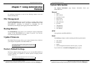
Serial Bridge
Select Serial Bridge to implement Paired Mode (also called serial
tunneling). This allows serial devices connected to two PES1A/PESV1A
converters to communicate across the network. The two PES1A/PESV1A
converters automatically connect to each other.
Terminal
Select Terminal to communicate with the PES1A/PESV1A via its serial port
using a terminal program and a command line interface. For more
information on this option and the command line interface contact B&B
Electronics Technical Support.
Modem Emulation
Select Modem Emulation to configure the serial port to operate as if it is a
modem. For legacy applications where a serial device is set up to
communicate through a modem, the serial device can be connected to the
PES1A/PESV1A and communication occurs over the network. The
PES1A/PESV1A emulates modem responses to and from the serial device.
Custom
Select Custom to custom configure the PES1A/PESV1A serial port and is
used if your application does not fit into any other predefined modes. This is
an advanced option that allows full configuration of the serial port.
Apply
After you have selected a port profile, click the Apply button. The Serial
Port Configuration page will re-appear and will contain additional
configuration settings specific to the profile you have chosen.
For more information on these configuration options see the web-based Tutorial
and online Help.
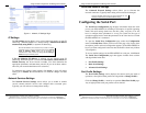
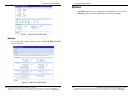
Basic Serial Settings
Click the Basic Serial Settings menu bar on the Serial Port Configuration
page to configure the PES1A/PESV1A’s serial port Baud Rate, Data Bits,
Parity, Stop Bits and Flow Control parameters. For all profiles except
RealPort, the Basic Serial Settings configuration section allows you to set
these parameters. When the RealPort profile is selected the serial port
settings will be directed by the PC applications using the virtual COM port.
Using the Web Configuration and Management Interface
24 Manual Documentation Number: PES1A/PESV1A-4905m
B&B Electronics Mfg Co Inc – 707 Dayton Rd - PO Box 1040 - Ottawa IL 61350 - Ph 815-433-5100 - Fax 815-433-5104 – www.bb-elec.com
B&B Electronics Ltd – Westlink Commercial Park – Oranmore, Galway, Ireland – Ph +353 91-792444 – Fax +353 91-792445 – www.bb-europe.com
Advanced Serial Settings
Click the Advanced Serial Settings menu bar to access settings used to fine
tune the serial port. Typically these setting will not need to be changed.
Consult the web-based tutorial for more information if necessary.
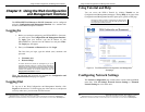
Configuring Alarms and Notification
The PES1A/PESV1A can be configured to generate alarms and send
notification emails based on the occurrence of specific events. Events include
the states of some RS-232 handshake (GPIO) lines and the detection of
specified character patterns within the serial data stream. The Alarms
Configuration page displays the current alarm settings and allows you to
configure them. It contains two sections: Alarm Notification Settings and
Alarm Conditions.
Note: In the PES1A/PESV1A GPIO lines are permanently configured as RS-
232 hardware handshake lines to support the standard RS-232 interface. Do
not attempt to re-configure the settings in the GPIO section of the Web
Configuration and Management Interface.
Alarm Notification Settings
The Alarm Notification Settings page provides a checkbox to enable alarm
notifications. Text boxes are provided to enter the IP address of your SMTP
mail server and the email address that will be placed in the From field of the
email.
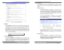
Alarm Conditions
The Alarm Conditions page is a tabular listing of 32 alarms that can be
configured. Table headings include Enable (a checkbox), Alarm
name/number, Type of alarm, Trigger conditions, SNMP Trap, Send to
address and Email Subject line.
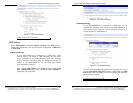
Clicking on the Alarm name opens an Alarm Configuration page for that
specific alarm. The page contains two sections: Alarm Conditions and
Alarm Destinations.
Alarm Conditions allows you to select GPIO-based or serial data pattern-
based events.