


Introduction
Manual Documentation Number: ESP901-902_4105m Chapter 1 5
B&B Electronics Mfg Co Inc – 707 Dayton Rd - PO Box 1040 - Ottawa IL 61350 - Ph 815-433-5100 - Fax 815-433-5104 – www.bb-elec.com
B&B Electronics Ltd – Westlink Commercial Pk – Oranmore, Galway, Ireland – Ph +353 91-792444 – Fax +353 91-792445 – www.bb-europe.com
Serial Server Quick Start Guide
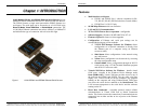
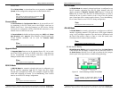
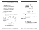
For descriptive purposes this Quick Start Guide considers a typical
configuration consisting of a PC connected via an Ethernet LAN to an
ESP901 or ESP902 Serial Server connected to the RS-232 port of a
serial device.
Hardware Setup
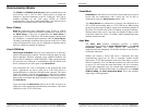
Figure 2. Typical Hardware Setup
Step 1: Connect the Serial Server to the network using a standard
network cable.
Step 2: Connect the
Serial Server to the RS-232 port on the serial
device.
N
N
o
o
t
t
e
e
:
:
If the serial device is configured as a DCE use a straight-through serial
cable. If the serial device is configured as a DTE use a crossover (null
modem) cable.
Step 3: Set all the DIP switches to the OFF position.
Step 4: Apply power to the
Serial Server.
Introduction
6 Chapter 1 Manual Documentation Number: ESP901-902_4105m
B&B Electronics Mfg Co Inc – 707 Dayton Rd - PO Box 1040 - Ottawa IL 61350 - Ph 815-433-5100 - Fax 815-433-5104 – www.bb-elec.com
B&B Electronics Ltd – Westlink Commercial Pk – Oranmore, Galway, Ireland – Ph +353 91-792444 – Fax +353 91-792445 – www.bb-europe.com
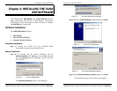
Software Installation
Using the CD included with the Serial Server, install the VLINX ESP
Manager
software on the configuring computer.
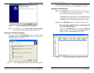
Serial Server Configuration
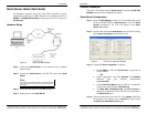
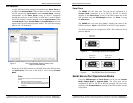
Step 1: Open the ESP Manager software. It will automatically search
for any reachable (ESP90x) Serial Servers. A list of all Serial
Servers
connected to the LAN will appear in the Serial
Server List window.
Step 2: Double click the desired
Serial Server port on the list to bring
up the
Server Properties configuration screen.
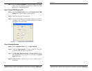
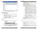
Figure 3. The Server Properties Window
Step 3: Change the Server Properties as required.
• Enable
DHCP to allow the Serial Server to generate its
own IP address
OR
• Obtain appropriate static
IP, Netmask and Gateway
addresses from your Network Administrator
(recommended)
• Set the
Serial Port Mode property to RS-232 to match the
serial device connected to the Serial Server.
• Set
Baud Rate, Data/Parity/Stop, and Flow Control to
match the configuration of the serial device connected to
the
Serial Server port
Step 4: When the parameters have been set, click
Update. Following
the prompts in the dialogue boxes,
Restart the Serial Server
and Search all reachable servers again.