


1
Installation
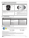
1. The MS-08 may be mounted in conventional metal or plastic
electrical gang boxes. Make sure the unit sensor does not come in
contact with the metal gang box to avoid shorting out the unit.
• Do not place the sensor in the door’s opening range, where the
sensor may see door movement.
• Do not place moving objects in front of the sensor.
2. Depending on the door installation, the weather resistant foam
gasket or the plastic adapter ring may be used. The weather
resistant foam is used as a protective barrier against the elements.
The plastic adapter ring is designed to enable the double gang face
plate to attach to various plastic and metal gang boxes.
2
Wiring
1. Wire the 4-conductor cable to the door operator according to
manufacturer specifi cations.
2. Attach the 4-conductor cable connector to the Magic Switch.
3 Precautions
Shut off all power going to wall outlet before attempting any wiring procedures.
Maintain a clean & safe environment when working in public areas.
Constantly be aware of pedestrian traffi c around the door area.
Always stop pedestrian traffi c through the doorway when performing tests that may result in unexpected reactions by the
door.
ESD electrostatic discharge: Circuit boards are vulnerable to damage by electrostatic discharge. Before handling any board
ensure you dissipate your body’s charge.
Always check placement of all wiring before powering up to insure that moving door parts will not catch any wires and cause
damage to equipment.
Ensure compliance with all applicable safety standards (i.e. ANSI A156.10 / A156.19) upon completion of installation.
DO NOT attempt any internal repair of the sensor. All repairs and/or component replacements must be performed by BEA,
Inc. Unauthorized disassembly or repair:
1. May jeopardize personal safety and may expose one to the risk of electrical shock.
2. May adversely affect the safe and reliable performance of the product will result in a voided product warranty.
4 Pre-Installation Check
1. When wiring multiple devices together creating a system confi guration, it is best to ensure that each device works independently. This will
reduce troubleshooting if a discrepancy occurs.
2. Prior to installing any equipment in either new or existing circuits, ensure correct line voltage and line stability. Always remember to shut the
power OFF before performing circuit wiring.
5 Installation / Wiring / Setup
Page 2 of 3 75.5265.01 20071031
M
S
0
8
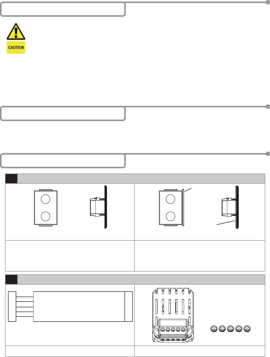
• PWR: Black - 12 to 24 VAC / VDC: -5% to +10%
• PWR: Red - 12 to 24 VAC / VDC: -5% to +10%
•
NC: Empty - NC Contact
• NO: Green - NO Contact
• COM: White - Common at Door Control
C
O
N
T
R
O
L
NC NOCOMPOWER
Gang Box
Metal or Plastic
MS-08
Assembly
Gang Box
Metal or Plastic
MS-08
Assembly
Adapter Ring
Foam Gasket
NC NO COM POWER
Black - 12 to 24 VAC / VDC
Red - 12 to 24 VAC / VDC
White - Com at Door Control
Green - NO Contact
Empty - NC Contact