


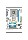
P4M800 Pro-M7
12
CHAPTER 3: HEADERS & JUMPERS SETUP
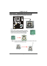
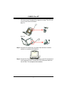
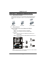
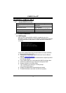
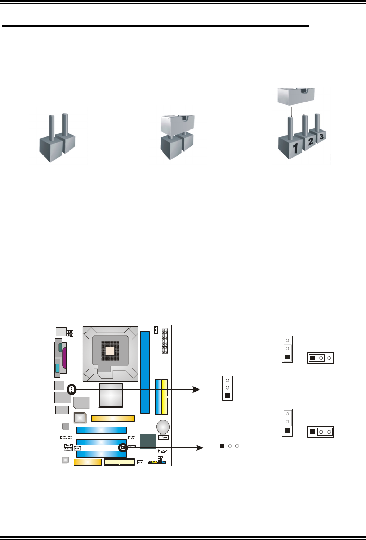
3.1 HOW TO SETUP JUMPERS
The illustration shows how to set up jumpers. When the jumper cap is
placed on pins, the jumper is “close”, if not, that means the jumper is
“open”.
Pin opened Pin closed Pin1-2 closed
3.2 DETAIL SETTINGS
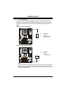
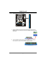
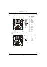
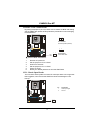
JUSBV1/JUSBV2: Power Source Headers for USB ports
Pin 1-2 Close:
JUSBV1: +5V for USB ports at JUSB1 and JUSBLAN1.
JUSBV2: +5V for USB ports at front panel (JUSB2/JUSB3).
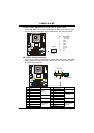
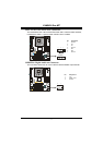
Pin 2-3 Close:
JUSBV1: USB ports at JUSB1 and JUSBLAN1 are powered by +5V
standby voltage.
JUSBV2: USB ports at front panel (JUSB2/JUSB3) are powered by +5V
standby voltage.
3
1
3
1
Pin 1-2 Close (Default)
JUSBV1
1
3
JUSBV2
13
3
1
3
1
Pin 2-3 Close
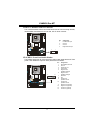
Note:
In order to support this function “Power-On system via USB device,” “JUSBV1/ JUSBV2”
jumper cap should be placed on Pin 2-3 individually.