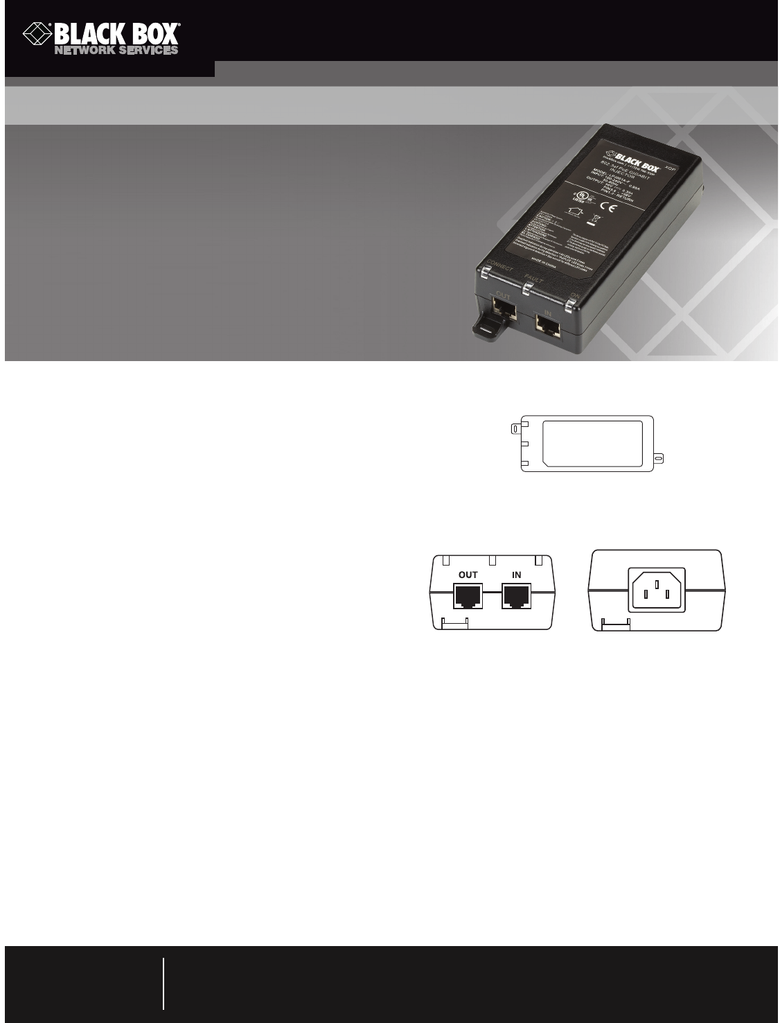
Exceeds the 802.3af standard.
Use with IP telephones, wireless access
points, IP print servers, IP cameras,
and Bluetooth
®
access points.
Order toll-free in the U.S.: Call 877-877-BBOX (outside U.S. call 724-746-5500) •
FREE technical support 24 hours a day, 7 days a week: Call 724-746-5500 or fax 724-746-0746 •
Mailing address: Black Box Corporation, 1000 Park Drive, Lawrence, PA 15055-1018 •
Web site: www.blackbox.com • E-mail: info@blackbox.com
Customer
Support
Information
LPJ001A-F
802.3af PoE Gigabit Injector, 1-Port
1. Specifications
Compliance: cUL/UL
®
; RoHS
Load (Maximum): 0.35 A
Regulation: Line and Load: 54–57 VDC under all
conditions
Connectors: Data in: (1) RJ-45 (10/100/1000);
Data/PoE out: (1) RJ-45 (10/100/1000);
Power: (1) IEC 320 (3-pin)
Indicators: (3) LEDs: (1) ON, (1) CONNECT, (1) FAULT
Power: AC input voltage range: 90–264 VAC;
AC input voltage rating: 100–240 VAC, 47–63 Hz;
Output: 19.6 W at 56 VDC
Size: 1.4"H x 2.6"W x 5.5"D (1 x 6.6 x 14 cm)
Weight: 0.4 lb. (0.2 kg)
2. Overview
The LPJ001A-F is a high-powered Gigabit power injector
that exceeds the IEEE 802.3af power standard. The injector provides
up to 19.6 W of power.
Use the LPJ001A-F with IP telephones, wireless access points, IP print
servers, IP cameras, and Bluetooth access points.
3. Setting Up Your Power Injector
NOTE: Use CAT5e or higher Ethernet cables (not included).
1. Using screws, affix the metal feet on the front and/or rear to a
flat surface such as a table or wall. See Figure 1.
NOTE: The power injector should not use the weight
of the Ethernet cables for support.
Figure 1. Location of metal feet on the power injector.
Power and Data in
data out
Front panel.
IEC-320 power connector.
Back panel.
Figure 2. Ports on the power injector.
2. Connect the 3-pin IEC320 AC input connector to a
power source. Power on the injector.
3. Using CAT5e or higher cable, connect the RJ-45 port
on the injector labeled “IN” to your network switch.
See Figures 2 and 3.
4. Connect the RJ-45 port labeled “OUT” on the injector over
Ethernet cable to the powered device. See Figures 2 and 3.
5. The LEDs will light to diagnose the connection. See Tables 1
and 2.
Figure 3. Cable connections to the power injector.
Insert a screw to
secure the unit
to a surface
Insert a screw
to secure the unit
to a surface
