


Installation
1. Turn off the PCs and monitors.
2. Connect the HD-15 video extension cable between
the VGA card of PCs and the “Video In” ports of
video matrix.
3. Connect the HD-15 video extension cables between
the monitors and the “Video Out” ports of video
matrix.
4. Connect the power cord and turn on the video
matrix.
5. Turn on the PCs and monitors.
6. Control front panel switch to obtain the image either
come from PC ○
A
(Linked LED “○
A
” on) or PC ○
B
(Linked LED “○
B
” on) or just switching off. (Linked
LED “○
A
○
B
” off)
Note:
All the “Video Out” ports will connect with the “Video
In” port of ○
A
while turning on the video matrix.
If you install the DDC monitor for the video matrix, the
rest of monitors must be the same resolution as the
DDC monitor.
Through the functionality of DDC monitor, the “Video
In” port of ○
A
will connect with the “Video Out” port 1
and the “Video In” port of ○
B
will connect with the
“video out” port 2.
Available monitors include the VGA, SVGA, XGA,
Multisync, and exclude the CGA, EGA, Mono.
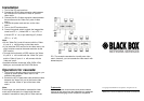
Operation for cascade:
1. The function to display image on more monitors, you
request to attach another video matrix or the
standard video splitter.
2. Connect the HD-15 male/male video extension cable
between the “Video Out” port of the former video
matrix and the “Video In” port of the latter video
matrix.
Note:
Even though you are allowed to cascade the video
matrix with varied ports, the image might become
unstable if cascade too many tiers of video matrixes.
P.S.: The example cascades the 4 and 8 ports video
matrix; however, you can cascade the video matrix with
demanded port.
Trademarks:
All the companies, brand names, and product names
referred to this manual are the trademarks or registered
trademarks belonging to their respective companies.
© Copyright 2004. Black Box Corporation. All rights reserved.
1000 Park Drive · Lawrence, PA 15055-1018 · 724-746-5500 · Fax 724-746-0746