


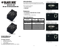
Installation
1. Turn off the PC and monitor.
2. Connect the DVI male/male extension cable between
the PC and the “DVI In” port of Local.
3. Connect the DVI male/male extension cable between
the monitor and the “DVI Out” port of Remote.
4. Connect the CAT.5 cable between the Local “CAT.5” port
and the Remote “CAT.5” port of extender.
5. Connect the power cord and turn on the extender.
6. Turn on the PC and monitor.
Technical Specifications
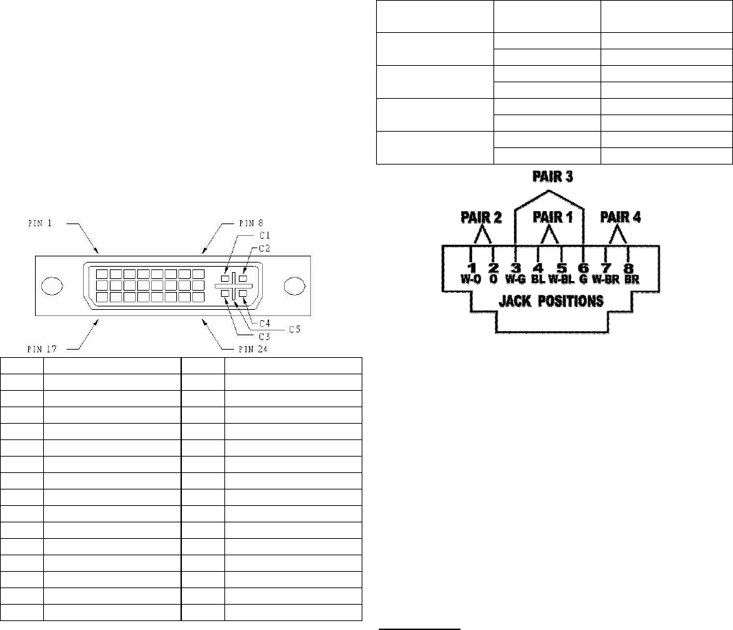
Input/Output Signal
Pin # Signal Pin # Signal
1
T.M.D.S Data 2-
16
Hot Plug Detect
2
T.M.D.S Data 2+
17
T.M.D.S Data 0-
3
T.M.D.S Data 2/4 Shield
18
T.M.D.S Data 0+
4
T.M.D.S Data 4-
19
T.M.D.S Data 0/5 Shield
5
T.M.D.S Data 4+
20
T.M.D.S Data 5-
6
DDC Clock
21
T.M.D.S Data 5+
7
DDC Data
22
T.M.D.S Clock Shield
8
Analog Vert. Sync
23
T.M.D.S Clock+
9
T.M.D.S Data 1-
24
T.M.D.S Clock-
10
T.M.D.S Data 1+
11
T.M.D.S Data 1/3 Shield
C1
Analog Red
12
T.M.D.S Data 3-
C2
Analog Green
13
T.M.D.S Data 3+
C3
Analog Blue
14
+5V Power
C4
Analog Horz Sync
15
GND
C5
Analog Ground
-3-
Wiring Information & Coding
Conductor
Identification
RJ45 Pin
Assignment
Color Code for
Conductor
5 White-Blue
Pair 1
4 Blue
1 White-Orange
Pair 2
2 Orange
3 White-Green
Pair 3
6 Green
7 White-Brown
Pair 4
8 Brown
Trademarks:
All the companies, brand names, and product names
referred to this manual are the trademarks or
registered trademarks belonging to their respective
companies.
-4-