


17
CHAPTER 4: Installation
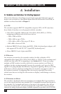
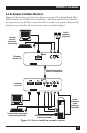
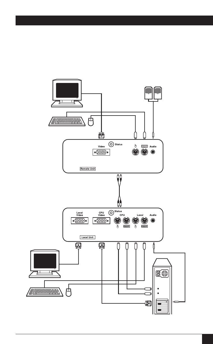
4.2 An Extender Installation Illustrated
Figure 4-1 shows where to attach your devices in a typical ServSwitch Brand Fiber
KVM Extender II or II-SM system installation. (The front panels of the extenders
are shown here; the SC fiber connectors will be on their rear panels.) Refer to this
illustration as you follow the instructions in the rest of this chapter.
Figure 4-1. How to install an extender system.
Active
speakers
(optional)
Extender
remote unit
Extender
local unit
Duplex fiber cabling
with SC connectors
Audio-
extension
cable
(optional,
included)
VGA and PS/2 extension
cables (included)
Remote
monitor,
keyboard,
and mouse
Local monitor, keyboard,
and mouse (optional)