


Express Ethernet Switch
16
Installation
Quick Tip
Install a Black Box Express Ethernet Switch as a plug-and-play device. No special
configuration is required. Details below are consistent with the installation of any electronic
device
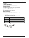
Place the Black Box Express Ethernet Switch where it will not be subjected to extreme
temperatures, humidity, or electromagnetic interference. Specifically, the site you select
should meet the following requirements:
?? The room temperature should be between 32 and 104 degrees Fahrenheit (0 to 40
degrees Celsius).
?? The relative humidity should be less than 90 percent, non-condensing.
?? Surrounding electrical devices should not exceed the electromagnetic field (RFC)
standards for IEC 801-3, Level 2 (3V/M) field strength.
?? Make sure that the switch receives adequate ventilation. Do not block the ventilation
holes on the side of the switch or the fan exhaust port on the rear of the switch.
?? The power outlet should be within 1.8 meters of the switch.
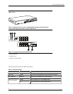
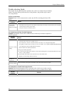
Connecting to Power
Connect the supplied AC power cord to the receptacle on the back of the switch, and then
plug the cord into a standard AC outlet with a voltage range from 100 to 120 VAC. For
external power supply units, plug the jack into the DC receptacle on the front of the unit,
and plug the power supply unit into a 110~220 AC outlet.
Turn the switch on by flipping the ON/OFF switch on the rear of the unit to the I (ON)
position. The O position is OFF.
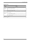
Connecting to Your Network
If you are making a connection to a server or workstation, be sure that it has a properly
installed 100BASE-TX (or 100BASE-FX if the switch does not contain 100BASE-TX
ports) network interface card. Connect the RX/TX jacks on the target device to the TX/RX
jacks on the switch and the RJ-45 jacks on the target device to the RJ-45 jacks on the
switch.
Use the uplink port for connecting to a regular (i.e. non-uplink) port of a hub or another
switch. If connecting to an uplink port of a hub or another switch, use any port. There is no
uplink issue with fiber ports.
Copper-based cabling
Connect cables to computers or network segments into the RJ-45 ports on the front of the
switch.
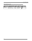
The cable must be a Category 5 shielded twisted-pair or unshielded twisted-pair (STP/UTP)
cable for 100BASE-TX, or Category 3, 4, or 5 STP/UTP cable for 10BASE-T. Consult
Table 9 for further details.
Fiber-optic cabling
Prepare a pair of fiber optic cables with SC or ST type connectors at both ends. The cable
for fiber ports must be a 62.5/125 micron fiber-optic cable for 100BASE-FX. Consult Table
9 for further details.