


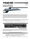

RJ45 EXPANSION MODULE FOR AFFINITY SERVSWITCH™
• Set JP1 and JP2 both to the DOWN position if you want the Affinity system to recognize any user on slot (port
card) 1 as “KVM 1,” any user on slot (port card) 2 as “KVM 2,” and so on. (This is the default setting.)
• Set JP1 and JP2 both to the UP position if you want the Affinity system to recognize any user on slot 1 as
“KVM5,” any user on slot 2 as “KVM 6,” and so on. We recommend that, unless the placement of your user
equipment demands otherwise, you set the user ports to KVM 1 through 4 on your first 8-User Affinity chassis,
KVM 5 through 8 on your second chassis, KVM 1 through 4 again on your third chassis, KVM 5 through 8 again
on your fourth chassis, and so on.
If a pair of cards is going into a 16-user Affinity chassis, follow the directions printed on the cards’ circuit boards:
• To assign the users on the chassis’ slots (port cards) 1 through 4 to “KVM 1” through “KVM 4” respectively, set
JP1 and JP2 on the “lower card” (the one you’ll install in the bottom slot) to the DOWN position and remove the
jumpers from JP1 and JP2 on the “upper card” (the one you’ll install in the top slot).
• To assign the users on slots 1 through 4 to “KVM 5” through “KVM 8,” set JP1 and JP2 on the lower card to UP
and remove the jumpers from JP1 and JP2 on the upper card.
• To assign the users on slots 1 through 4 to “KVM 9” through “KVM 12,” remove JP1 and JP2 on the lower card
and set JP1 and JP2 on the upper card to DOWN.
• To assign the users on slots 1 through 4 to “KVM 13” through “KVM 16,” remove JP1 and JP2 on the lower card
and set JP1 and JP2 on the upper card to UP.
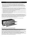
Once the expansions modules SW1 switch is set properly and JP1 and JP2 set for the assigned users, you can swap
the Expansion module for the termination Module. (Shipped from the factory with termination module installed).
Make sure that the Affinity ServSwitch is turned OFF and unplugged. Unscrew and remove the blank plate covering
the expansion card location. Carefully pull the termination module out of the backplane connector and replace it with
the expansion module. Make sure that the expansion module is firmly inserted into the backplane connector.
Secure the expansion module to the chassis with the two tightening screws.
Once the expansion modules are installed in all units in your system, you can run the expansion cables.
Data IN to Data OUT cable – Industry standard UTP CAT5 cable
Bus OUT to Bus IN – Coax RJ45 Data cable (P/N KV130XXX)
To connect the Affinity ServSwitch in a BUS configuration, connect a standard CAT5 cable from the DATA OUT port
on the last unit in the system to the DATA IN port on the next to the last unit in the system and so on for all units in
the system. The daisychain must end with a switch that has the KVM station for this bus.
DO NOT CONNECT A CABLE FROM THE FIRST UNIT’S DATA OUT TO THE LAST UNIT’S DATA IN TO FORM
A RING. MAKE SURE ONLY THE FIRST AND LAST UNITS ARE TERMINATED BY TURNING ON SW1.
Daisy chaining the units together in a BUS topology is accomplished by connecting expansion cables from the BUS1
OUT and BUS2 OUT to the BUS1 IN and BUS2 IN connectors for all units in the daisy chain.
Refer to the operations manual for detailed installation instructions.