


15
CHAPTER 2: Introduction
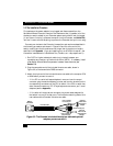
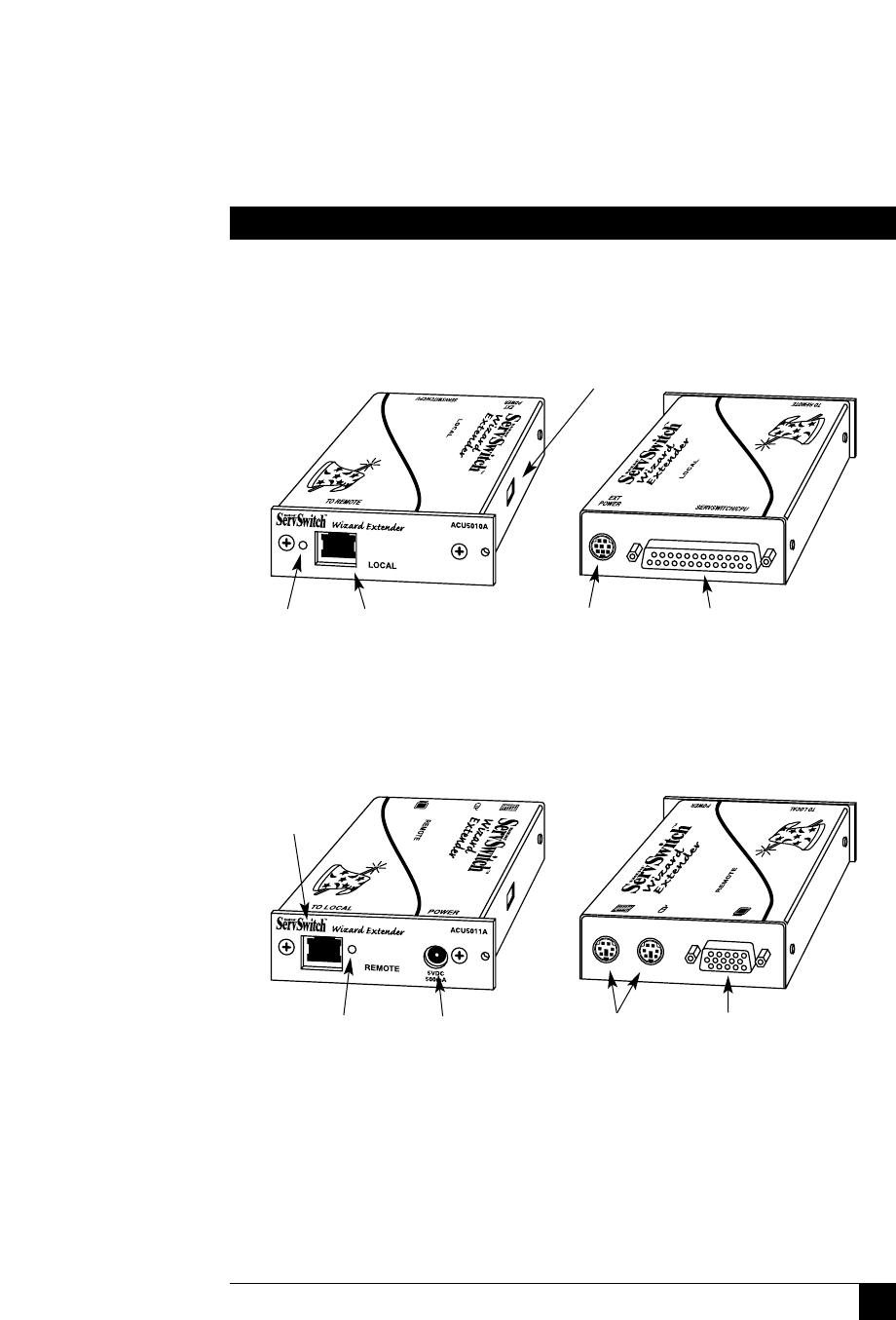
2.3 The Extender Illustrated
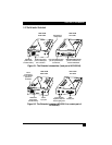
Figure 2-1. The Extender’s transmitter (local part of ACU5010A).
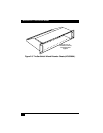
Figure 2-2. The Extender’s receiver (ACU5011A or remote part of
ACU5010A).
DIP switch for
configuration
VIEW FROM
RIGHT SIDE
VIEW FROM
RIGHT SIDE
VIEW FROM
LEFT SIDE
VIEW FROM
LEFT SIDE
LED shows
power status
and data activity
LED shows
power status
and data activity
Power-
input port
6-pin mini-DIN
keyboard (left) and
mouse (right) ports
HD15
monitor port
8-pin mini-DIN expansion
port for optional future
connections
DB25 SERVSWITCH/CPU
port for connection to a
CPU or KVM switch
RJ-45 interconnect
port for twisted-pair
link to receiver
RJ-45
interconnect
port for twisted-
pair link to
transmitter