


25
CHAPTER 3: Configuration
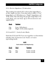
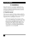
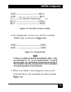
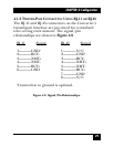
XMT+----------------------------------------RCV+
XMT- --------------------------------------- RCV-
G-------------To Shield (Optional) G
RCV+-----------------------------------------XMT+
RCV - ----------------------------------------XMT-
Figure 4-3. Two-Pair Crossover Cable.
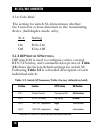
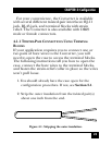
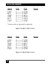
6. In a single-pair circuit, use only the transmit
(XMT) pair as shown in Figure 4-4.
XMT+------------------------------------------XMT+
XMT - -----------------------------------------XMT-
Figure 4-4. Transmit Pair.
NOTE
If there is a shield around the twisted-pair cable, it may
be connected to “G” on the terminal block. To avoid
ground loops, we recommend connecting the shield at
the computer end only. A ground wire is not necessary
for proper operation of the Converter.
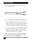
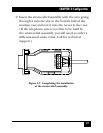
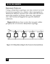
7. When you finish connecting the wires to the
terminal block, the assembly should resemble
Figure 4-5.