


MED100A 304 pg. 2 / 4 6132-r1
Black Box Corporation - 1000 Park Drive - Lawrence, PA 15055-1018
Tech Support and Ordering: 724-746-5500 - Fax: 724-746-0746
To contact us about Black Box products or services: info@blackbox.com
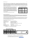
Table 1: RS
-
485 Timeout Selection
Baud Rate
Pos. 1 Pos. 2 Pos. 3 Pos. 4 Pos. 5 R9 Time(ms)
1200
ON OFF OFF OFF OFF
820 KΩ
8.20
2400
ON OFF OFF OFF OFF
430 KΩ
4.30
4800
OFF OFF OFF OFF ON Not Used 2.20
9600
OFF OFF OFF ON OFF Not Used 1.30
19.2K
OFF OFF ON OFF OFF Not Used 0.56
38.4K
OFF ON OFF OFF OFF Not Used 0.27
57.6K
ON OFF OFF OFF OFF Not Used 0.22
76.8K
ON OFF ON ON OFF Not Used 0.14
115.2K
ON ON ON OFF OFF Not Used 0.10
153.6K
ON OFF OFF OFF OFF
6.2 KΩ
0.06
230.4K
ON OFF OFF OFF OFF
4.3 KΩ
0.04
460.8K
ON OFF OFF OFF OFF
2.2 KΩ
0.02
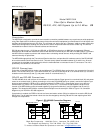
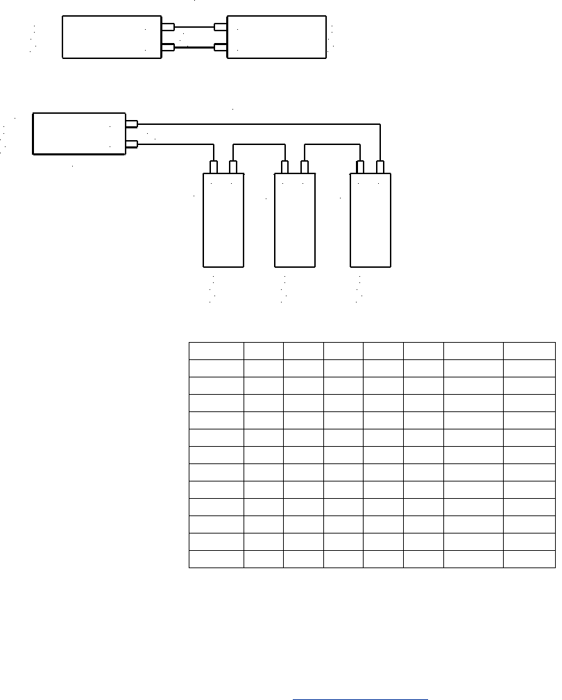
Fiber Optic Connections
The MED100A uses a separate LED emitter and photo-detector operating at 820 nm wavelength. Connections to the
emitter and detector are on ST type connectors. Most multimode glass fiber size can be used including 50/125 µm,
62.5/125 µm, 100/140 µm, and 200 µm. One fiber is required for each connection between a transmitter and receiver. In a
point to point configuration, two fibers are required between the two modems, one for data in each direction. A multi-drop
ring configuration requires one fiber between TX and RX around the loop. See Figure 2 for typical point-to-point and multi-
drop configurations.
The most important consideration in planning the fiber optic link is the “power budget” of the fiber modem. This value
represents the amount of loss in dB that can be present in the link between the two modems before the units fail to
perform properly. This value includes line attenuation as well as connector loss. For the MED100A the typical connector to
connector power budget is 12.1 dB. Because 62.5/125 µm cable typically has a line attenuation of 3 dB per Km at 820 nm,
the 12.1 dB power budget translates into 2.5 miles. This assumes no extra connectors or splices in the link. Each extra
connection would typically add 0.5 dB of loss, reducing the possible distance by 166 m (547 ft.). The actual loss should be
measured before assuming distances.
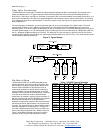
Figure 2: Typical Setups
TX
RX
FOSTCDR
RX
TX
FOSTCDR
RS-232
RS-422
or RS-485
Device
Duplex
Multimode
Fiber
or System
RS-232
RS-422
or RS-485
Device
or System
SW1:6 = OFF SW1:6 = OFF
Point to Point
TX
RX
FOSTCDR
RX
TX
FOSTCDR
RS-232
RS-422
or RS-485
Device
Multimode
Fiber
or System
RS-232
RS-422
or RS-485
Device
or System
RX
TX
FOSTCDR
RS-232
RS-422
or RS-485
Device
or System
RX
TX
FOSTCDR
RS-232
RS-422
or RS-485
Device
or System
Full Duplex
SW1:6 = OFF
SW1:6 = ON
SW1:6 = ON
SW1:6 = ON
MASTER
SLAVE
SLAVE
SLAVE
Multi-Drop Ring
Dip-Switch Setup
The Dip-Switch (SW1) on the MED100A defines the
mode of operation when being used for RS-422 or RS-
485. Positions 1 through 5 on the switch determine the
timeout of the RS-485 driver. Because the driver is
controlled by hardware, a specific time must be set to
tell the hardware how long to wait for data on the fiber
side before turning off the RS-422/485 driver. If this time
is set too short, the driver could be disabled before
transmission is complete, resulting in data corruption. If
the time is set too long, the RS-485 device may respond
before the RS-422/485 driver in the MED100A is
disabled, corrupting this response. We recommend that
the timeout be set for approximately one character time
or longer. The character times for several different baud
rates are selectable on switch positions 1 through 5. If
you need a different timeout than what is provided, R10
can be removed and replaced with a different value R9.
Table 1 shows different timeout values for the switch
positions as well as typical R9 replacement values.
MED100A
SW1:6=OFF
MED100A
SW1:6=OFF
MED100A
SW1:6=OFF
MED100A
SW1:6=ON
MED100A
SW1:6=ON
MED100A
SW1:6=ON