


3 of 4
6/14/07
#10470
724-746-5500 blackbox.com
IEEE 488.
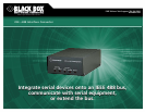
IEEE 488 (also known as GPIB or General Purpose Interface
Bus) is an international standard for a parallel interface
that has greatly simplified the connection of sensors and
programmable instruments to a computer. With it, instru-
ments from different manufacturers can be connected by
a single standard cable.
Two IEEE 488 standards are in use: the older IEEE 488.1
standard, which deals with the hardware only, and the newer
IEEE 488.2 standard, which also addresses software issues like
data formats and error handling.
IEEE 488.1 is a clearly defined mechanical, hardware,
and electrical protocol specification. It doesn’t address data
formats, status reporting, message-exchange protocol, or
common configuration or device-specific commands.
IEEE 488.2 enhances the IEEE 488.1 standard by specifying
data formats, status reporting, error handling, controller
functionality, and common instrument commands. It focuses
mainly on the software protocol issues and thus maintains
compatibility with the hardware-oriented IEEE 488.1
standard. IEEE 488.2 systems tend to be more compatible
and reliable.
Most devices can be adapted to the IEEE 488 specification.
The specification says nothing about the function of the
device itself, or about the form of the device’s data. Instead,
it defines a separate interface that can be added to the
device. Only the signals passing into the interface from the
IEEE 488 bus and from the device are defined in the standard.
There are three classes of devices that can be connected
to the IEEE 488 bus: Listeners, Talkers, and Controllers.
Some devices include more than one of these functions.
The IEEE 488 standard allows a maximum of 15 devices to be
connected on one bus. A minimum system consists of one
Controller and one Talker or Listener device.
A Controller is the device that sends instructions. It’s
possible to have several Controllers on the bus at once but
only one may be active at a time. The Controller that’s in
charge at the moment is called the Active Controller.
The Controller that’s in charge of the entire bus is called
the System Controller. It has several unique capabilities,
including the ability to send Interface Clear (IFC) and Remote
Enable (REN) commands. IFC clears all device interfaces
and returns control to the System Controller. REN allows
devices to respond to bus data once they are addressed to
listen. The System Controller may optionally pass control to
another Controller, which then becomes the Active Controller.
A Listener is a device that can receive data from the bus
when instructed by the Controller. A Talker transmits data on
the bus when instructed. The Controller can set up a Talker
and a group of Listeners to send data between groups of
devices.
The IEEE 488 interface system consists of 16 signal lines
and 8 ground lines. The 16 signal lines are divided into 3
groups (8 data lines, 3 handshake lines, and 5 interface-
management lines).
The lines DIO1 through DIO8 are used to transfer
addresses and control information and data. The formats
for addresses and control bytes are defined by the IEEE 488
standard. Data formats are undefined and may be ASCII
or binary. DIO1 is the Least Significant Bit.
The three handshake lines (NRFD, NDAC, DAV) control
the transfer of message bytes among devices and form the
method for acknowledging the transfer of data. This
handshaking process guarantees that bytes on the data lines
are sent and received without any transmission errors. It’s
one of the unique features of the IEEE 488 bus.
The Not Ready for Data (NRFD) handshake line is asserted
by a Listener to indicate it is not yet ready for the next data
or control byte. Note that the Controller will not see NRFD
released (meaning the devices are ready for data) until all
devices have released it.
The Not Data Accepted (NDAC) handshake line is asserted
by a Listener to indicate it has not yet accepted the data or
control byte on the data lines. Note that the Controller will
not see NDAC released (i.e., data accepted) until all devices
have released it.
The Data Valid (DAV) handshake line is asserted by
the Talker to indicate that a data or control byte has been
placed on the data lines and has had the minimum specified
stabilizing time. The byte can now be safely accepted by
the devices.
Five interface management lines (ATN, EOI, IFC, REN, SRQ)
manage the flow of control.
The Attention (ATN) signal is asserted by the Controller
to indicate that it is placing an address or control byte on the
data bus.
The End or Identify (EOI) signal has two uses. A Talker
may assert EOI simultaneously with the last byte of data to
indicate end-of-data. Or the Controller may assert EOI along
with ATN to initiate a parallel poll. Although many devices
do not use parallel poll, all devices should use EOI to end
transfers.
Technically Speaking