


9
CHAPTER 3: Installation
3. Installation
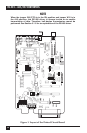
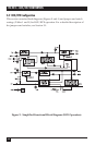
This section describes the jumper and switch functions for configuring the
RS-232↔485/422 Converter. See Figure 1 on the next page for the component
locations.
To install your RS-232↔485/422 Converter:
1. Set each of the ten jumpers/switches for your application.
2. Connect the RS-232↔485/422 Converter devices together as shown in
Figures 5 through 8 (pages 23–25).
3. Apply power. (PS154 or PS154E, depending on which RS-232↔485/422
Converter you have. See Chapter 1 for more information.)
3.1 Jumper and Switch Configuration
NOTE
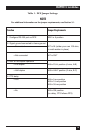
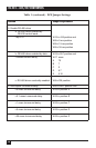
As you read this section, refer to Tables 1 and 2. Table 1 (page 15) lists
DCE jumper settings, and Table 2 (page 20) lists DTE jumper settings.
3.1.1 DTE/DCE C
ONFIGURATION
A DIP shunt is used to select DTE or DCE configuration. For the RS-232↔485/422
Converter to appear as a DTE device, put the DIP shunt jumper in socket XW1B.
For the RS-232↔485/422 Converter to appear as a DCE device, put the DIP shunt
jumper in socket XW1A.
3.1.2 F
RAME
G
ROUND
/S
IGNAL
G
ROUND
Jumper W7 ties signal ground to frame ground. The position is left open at the
factory. If signal ground is to be connected to frame ground, solder a 100-ohm,
1/2-watt resistor in location W7. A wire jumper may also be used. Care must be
taken to ensure that ground circulating currents are limited to acceptable levels.
3.1.3 H
ALF
/F
ULL
-D
UPLEX
O
PERATION
Jumper W8 selects half-duplex or full-duplex operation. Set W8 to the HALF
position (B-C position) for half-duplex operation. Set W8 to the FULL position
(A-B position) for full-duplex operation.