


14
RS-232↔485/422 CONVERTERS
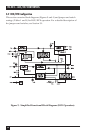
3.2 DCE/DTE Configuration
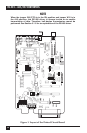
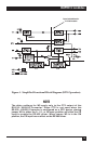
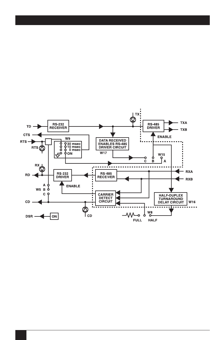
This section contains block diagrams (Figures 2 and 4) and jumper and switch
settings (Tables 1 and 2) for DCE/DTE operation. For a detailed description of
the jumpers and switches, see Section 3.1.
Figure 2. Simplified Functional Block Diagram (DCE Operation).