


724-746-5500 | blackbox.com
Page 7
IC502A
Chapter 2: Overview
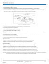
2.4 Hardware Description
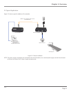
Figures 2-1 and 2-2 show the front and back panels of the Local Extender Unit. Table 2-1 describes the local extender
components. Figures 2-3 and 2-4 show the front and back panels of the Remote Extender Unit. Table 2-2 describes the remote
extender components.
2.4.1 Local Extender
The local extender connects to the host computer using the supplied USB 3.0 A–B cable.
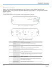
Figure 2-1. Front panel of the local extender.
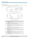
Figure 2-2. Back panel of the local extender.
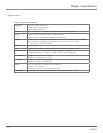
Table 2-1. Local Extender components.
Item Component Description
1 Power LED
ON when the unit is powered properly.
OFF when the unit is not powered or not powered properly.
2 Status LED
Blinking (1 Hz) when the local extender is waiting for a connection to the remote
extender.
ON when local and remote extenders are linked and operating normally.
OFF when a fault is detected; power cycle required.
3 Host LED
ON when a SuperSpeed Host is detected on the upstream port.
OFF when a SuperSpeed Host is not detected.
4 Power Port (optional)
Not required in normal operation. An optional 5-V power supply can be connected
to the local extender to provide power if the USB port on the host PC is not capable
of delivering sufficient power to the unit.
5 Config Port Reserved for manufacturer use.
6 USB 3.0 Type B port
Used to connect the local extender to the host computer. Port accepts locking or
non-locking USB 3.0 Type B connectors.
7 Link Port (Duplex LC) Extension link duplex LC fiber optic transceiver port.