


MED100A-0908-2/5 p/n 6132r3
Black Box Corporation - 1000 Park Drive - Lawrence, PA 15055-1018
Tech Support and Ordering: 724-746-5500 - Fax: 724-746-0746
To contact us about Black Box products or services: info@blackbox.com
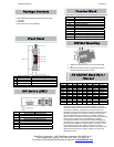
Package Contents
• MED100A Industrial Serial To Multi-mode Fiber Optic
Converter
• Datasheet
• Fiber Optic Dust Cover (installed)
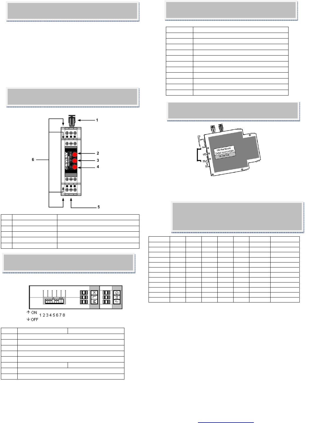
Front Panel
1 Fiber Connectors Multi-mode, ST Connectors
2 PWR LED ON When Power Applied
3 TD LED On When Serial Data Transmitted
4 RD LED On When Serial Data Received
5 DIP Switch 8 Position,
6 Terminal Blocks Serial Data and Power
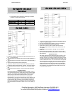
DIN Rail Mounting
1. Angle the converter DIN clip over the top of the DIN
rail.
2. Move the converter so that it is parallel with the DIN
Rail and snap the DIN clip into place..
DIP Switch (SW1)
Pos ON OFF
1 RS-422/485 Baud Rate Selection
2 RS-422/485 Baud Rate Selection
3 RS-422/485 Baud Rate Selection
4 RS-422/485 Baud Rate Selection
5 RS-422/485 Baud Rate Selection
6 FO Multi-drop Ring FO Point-to-Point
7 RS-422/485 Mode Selection
8 RS-422/485 Mode Selection
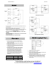
Terminal Block
Terminal Signal
A RS-232 RD (OUTPUT)
B GND
C GND
D RS-232 TD (INPUT)
E NOT CONNECTED
F +10 TO 30 VDC
G RS-422/485 TDA(-) / DATA A(-)
H RS-422/485 TDB(+) / DATA B (+)
J +10 TO 30 VDC
K RS-422/485 RDA(-) / DATA A (-)
L RS-422/485 RDB(+) / DATA B (+)
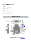
RS-422/485 Baud Rate /
Timeout
Baud 1 2 3 4 5 R9 TIME OUT
1200 ON OFF OFF OFF OFF 820 kΩ 8.20 ms
2400 ON OFF OFF OFF OFF 430 kΩ 4.30 ms
4800 OFF OFF OFF OFF ON None 2.20 ms
9600 OFF OFF OFF ON OFF None 1.30 ms
19.2K OFF OFF ON OFF OFF None 0.56 ms
38.4K OFF ON OFF OFF OFF None 0.27 ms
57.6K ON OFF OFF OFF OFF None 0.22 ms
76.8K ON OFF ON ON OFF None 0.14 ms
115.2 K ON ON ON OFF OFF None 0.10 ms
153.6K ON OFF OFF OFF OFF 6.2 kΩ 0.06 ms
230.4K ON OFF OFF OFF OFF 4.3 kΩ 0.04 ms
460.8K OF OFF OFF OFF OFF 2.2 kΩ 0.02 ms
The Dip-Switch on the MED100A defines the mode of operation
when being used for RS-422 or RS-485. Positions 1 through 5
determine the timeout of the RS-485 driver. Because the driver is
controlled by hardware, a specific time must be set to tell the
hardware how long to wait for data on the fiber side before turning
off the RS-422/485 driver. If this time is set too short, the driver
could be disabled before transmission is complete, resulting in
data corruption. If the time is set too long, the device may respond
before the RS-422/485 driver in the MED100A is disabled,
corrupting this response. Set the timeout for approximately one
character time or longer. The character times for several different
baud rates are selectable on switch positions 1 through 5. If you
need a different timeout than what is provided, R10 can be
removed and replaced with a different value R9. This table shows
different timeout values for the switch positions as well as R9
replacement values.