


Page 11
724-746-5500 | blackbox.com
Chapter 2: Overview
2.3.4 KV9614A Rear Panel
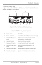
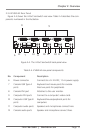
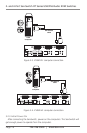
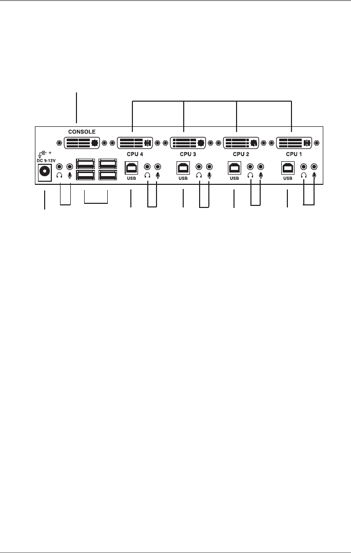
Figure 2-4 shows the 4-Port ServSwitch rear view. Table 2-4 describes the com-
ponents numbered in the illustration.
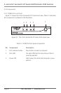
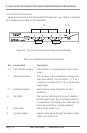
Figure 2-4. The 4-Port ServSwitch back-panel view.
Table 2-4. KV9614A rear-panel components.
No. Component Description
6 Power connector Connects to a 9–12-VDC, 1.5-A power supply.
7 Console USB Type A Keyboard and mouse ports for console.
ports Also two ports for peripherals.
8 Console DVI port Attaches to the user monitor.
9 Computer DVI ports Connect to a computer’s video cards.
10 Computer USB Type B Keyboard/mouse/peripheral ports for
ports computers.
11 Computer audio ports Speakers and microphones connect here.
12 Console audio ports Speaker and microphone connect here.
6
7
8
9
1012
11
11
1111
10
1010