


724-746-5500 | blackbox.com
Chapter 2: Overview
Page 9
2.4 Hardware Description
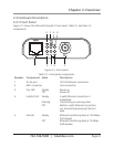
2.4.1 Front Panel
Figure 2-1 shows the Ethernet Extender’s front panel. Table 2-1 describes its
components.
1 5 7 9 2
4 3 6 8
Figure 2-1. Front panel.
Table 2-1. Front-panel components.
Number Component State Description
1 RJ-45 port 10/100 Ethernet connection
2 BNC connector Line connection
3 Pwr LED Steady Power on
Off Power off
4 Lnk/Act LED Steady A valid Ethernet connection is
established
Flashing Transmitting or receiving data
Off Neither a valid Ethernet connection
nor transmitting/receiving Ethernet
data.
5 Fdx LED Steady Ethernet transferring data at 100 Mbps
(full-duplex)
Off Ethernet transferring data at 10 Mbps
(half-duplex)