


724-746-5500 | blackbox.com
Page 16
724-746-5500 | blackbox.com
Chapter 2: Overview
2.3.3 Paired Mode
Paired Mode is also called serial tunneling. In this mode, any two serial devices that can communicate with a serial link will be able
to communicate using two Serial Servers and the LAN.
Two Serial Servers are connected to a network, one configured as a TCP or UDP client and the other as a TCP/UDP server. When
setting up the server the remote IP address section must contain the address of the client. This will allow the client’s IP address to
pass the IP address-filtering feature of the server. Conversely, the Remote IP address of the client must contain the server’s IP
address. Both communication port numbers must be the same.
2.3.4 Heartbeat
The Heartbeat protocol connection provides a reliable communications connection in Virtual COM Port Mode or with Paired
Connection Mode. This feature restores the connection if communications are temporarily lost at either end because of loss of
power or Ethernet connection.
Without this feature, a device that loses a connection and stops communicating would not be able to reconnect without human
intervention. A TCP data connection can be lost when there is a power failure or temporary loss of an Ethernet connection on
either the client or server. If a loss occurs, the Heartbeat feature will try to reconnect the TCP data connection every five seconds
until communications are established again. The Heartbeat feature is available for use in Virtual COM Port Mode and Paired
Connection Mode. This is not available when using a UDP application.
2.4 What’s Included
Your package should contain the following items. If anything is missing or damaged, contact Black Box Technical Support
at 724-746-5500 or info@blackbox.com.
• 1-, 2-, or 4-Port Industrial Serial Server module.
• (1) CD-ROM containing Serial Server Manager and Virtual COM Driver software for Windows 2000/2003 Server/XP/
Vista/2008/Win 7 and this user manual in PDF format.
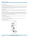
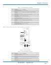
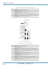
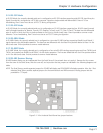
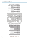
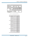
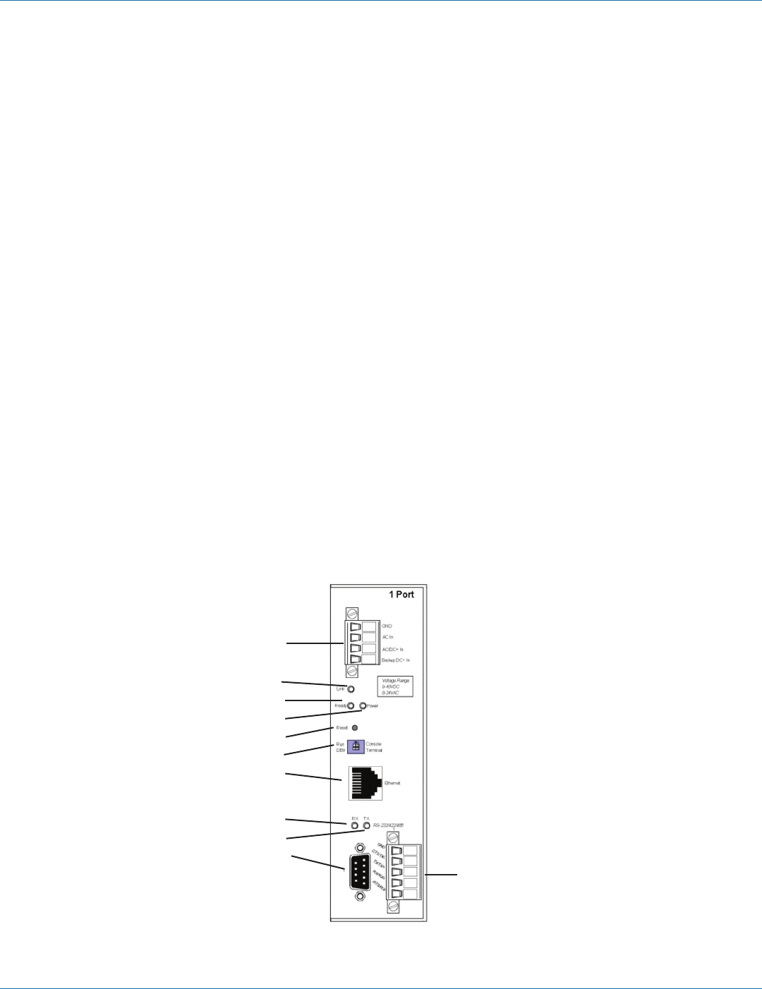
2.5 Hardware Description
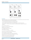
Figure 2-2 shows the 1-Port Serial Server. Table 2-1 describes its components.
1
2
3
4
5
6
7
8
9
10
11
Figure 2-2. 1-Port Serial Server.