


724-746-5500 | blackbox.com
724-746-5500 | blackbox.com
Page 43
Chapter 6: Operation
1
1
2
3
4
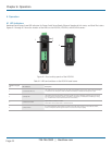
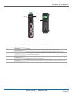
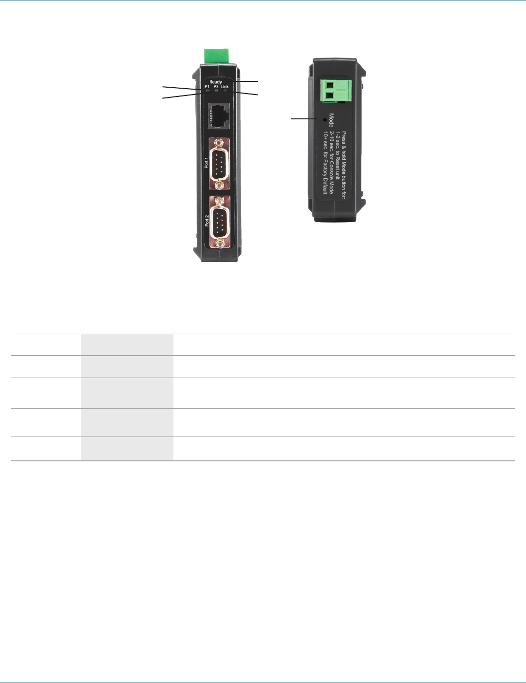
Figure 6-2. Front panel of the LES422A.
Table 6-2. LEDs and switches on the LES422A serial server.
Number in Figure
6-2 LED Indicator Description
1 (2) Serial Port LEDs (P1, P2)
Each serial port has an associated LED. The Serial Port LED flashes (green) when data is being
transmitted or received on the serial ports. When the LED is illuminated, it indicates the serial port is open.
2 (1) Ready LED
The Ready LED (green) illuminates continuously while the unit is initializing. It flashes once per second when the
system is operating correctly. If the LED is not flashing, it indicates that something is wrong (e.g., another device on
the network at the same IP address).
3 (1) Ethernet Link LED
Lights when a connection is made.
Flashes when there is data traffic on the Ethernet link.
4 (1) Reset switch
A recessed momentary Reset switch is located on the side of the enclosure. To activate the switch, insert a small
plastic tool through the hole in the enclosure and press lightly.