MED100A 304 pg. 3 / 4 6132-r1
Black Box Corporation - 1000 Park Drive - Lawrence, PA 15055-1018
Tech Support and Ordering: 724-746-5500 - Fax: 724-746-0746
To contact us about Black Box products or services: info@blackbox.com
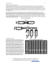
Table 2: 422/485 Switch Settings
Position 7
TX Enable
Position 8
RX Enable
RS-485
2-Wire Mode
(half duplex)
ON ON
RS-485
4-Wire Mode
(full duplex)
ON OFF
RS-422 Mode
(full duplex)
OFF OFF
Table 3: Recommended Maximum
MED100 in a Fiber Ring Topology
Baud Rate RS-232
Operation
RS-422/485
Operation
460.8 kbps N/A 2
230.4 kbps N/A 4
115.2 kbps 2 8
57.6 kbps 8 16
38.4 kbps 16 24
19.2 kbps
and lower 32 32
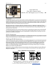
Position 6 of SW1 sets the unit in a “Multidrop” mode or a “Point-to-Point” mode. When the MED100A is set in a
“Multidrop” mode, data arriving on the Fiber Optic receiver is repeated back out the transmitter. When set in a “Point-to-
Point” mode, data arriving at the Fiber optic receiver is not sent back out the Fiber Optic transmitter. Position 6 must be
turned “On” when the MED100A is to be used in a multi-drop ring configuration. It must be turned “Off” when the
MED100A is to be used as either end of a point-to-point communication line. See Figure 3 for typical system setups using
the MED100A in its different modes.
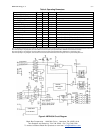
Positions 7 and 8 of SW1 determine when the RS-422/485 driver and
receiver are enabled. Position 7 controls the driver and Position 8
controls the receiver. For RS-422 operation, set both switches to the
“Off” position. For multi-drop RS-485 four-wire systems, position 7
should be “On” and position 8 should be “Off.” This allows the receiver
to be enabled all of the time and eliminates some possible timing
problems. For RS-485 two-wire systems, both switches should be in the
“On” position. This disables the RS-422/485 receiver whenever the
driver is enabled, preventing data from being echoed back to the fiber
side of the MED100A.
Table 2 illustrates the switch settings for typical setups.
Multi-drop Operation
A multi-drop configuration is created by forming a ring of MED100As. Each transmitter is tied to the following converter’s
receiver, starting at a master node and continuing around to each slave and back to the master. By setting SW1:6 to the
“On” position on the slaves, all data sent from the master or preceding slaves is echoed back out the fiber transmitter to
the rest of the slaves and eventually back to the master node.
Because all data is echoed back, there are special considerations when constructing a multi-drop system. The master will
see its own transmitted data. This means that the master device must be full-duplex (RS-232, RS-422, or four-wire RS-
485) and that it must be capable of ignoring or otherwise accepting its own echoed transmission. Slaves must also be
able to accept data from previous slaves in the loop.
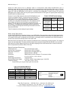
Specifications/Features
Transmission Line: Dual multimode optical cable
Point-to-Point Transmission: Asynchronous, half or full-duplex
Multi-Drop Transmission: Asynchronous, half duplex fiber ring
Interfaces: RS-232, RS-422, or RS-485
Connectors: DB25 female for serial connection, ST connectors for fiber
Dimensions: 4.3 x 2.3 x 0.95 in (11 x 5.9 x 2.5 cm)
Power Supply Connections: Terminal blocks
Recommended Power Supply: # PSD100 (12VDC, Input voltage range: 10-30 VDC)
Temperature Rating: -40 to +80°C (-40 to +176°F)
All specifications given using 62.5/125µm glass multi-mode fiber.
Model Number: MED100A
Description: DIN mount Fiber Optic Converter
Type: Light industrial ITE equipment
Application of Council Directive: 89/336/EEC
Standards: EN 55022
EN 61000-6-1
EN 61000 (-4-2, -4-3, -4-4, -4-5, -4-6, -4-8, -4-11)


