


2 of 4
5/25/2007
#12441
724-746-5500 blackbox.com
FEATURES
• Work via Telnet over a network,with
a browser and a modem, or serial
commands from a local console.
• Horizontal models occupy either
1U or 2U of space.
• Vertical models require zero-unit
mounting.
• Offer two levels of password security
plus encryption.
• Control outlet plugs individually.
Rackmount Remote Power Manager components.
OVERVIEW
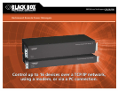
Remotely control up to 4, 5, 8, or 16 pieces of powered
equipment with BLACK BOX
®
Rackmount Remote Power
Managers.
Use an ASCII command line interface via Telnet
™
and a
TCP/IP network, a Web browser and a modem, or a local serial
PC console that’s emulating a terminal. The power manager’s
10BASE-T interface is used for network connections, and its
RS-232 port is used for modem or console connections.
Because these power managers have a network connection
for controlling them remotely, you can avoid having to make
a late-night service call simply to reboot a system or flip a
power switch. All you do is point your browser to its IP
address, enter a password, and power up (or down) or reboot
plugged-in equipment from your remote site.
The 4- and 5-outlet power managers each have one power
circuit, and the 8- or 16-port managers feature two power
circuits (A and B, consisting of Plugs 1–4 or 1–8 for Circuit A
or Plugs 5–8 or 9–16 for Circuit B). The maximum amps varies
by the model chosen (for details, see TECH SPECS on page 3).
Each outlet plug is individually controllable, so you can
switch just one piece of equipment, several devices, or all
connected devices at any time.
Choose either a horizontal or vertical power manager.
The horizontal models require only 1U or 2U of rack space;
the vertical models use zero units of space when mounting
to a rack.
You can also choose your power range: 105–120 VAC,
100–120 VAC, 208–240 VAC, or 105–240 VAC.
The power managers feature superior password
protection. A user level limits access for regular users to
assigned plugs, and an administrator level gives the system
administrator access to all configuration and switching
functions for maximum control. Plus, encryption protects
your valuable data from hackers.
You can configure Rackmount Remote Power Managers
over the TCP/IP network, through a modem link, or locally
through the console port. A standard JavaScript enabled
browser (such as Microsoft
®
Internet Explorer or Netscape
®
Navigator) or an ASCII text menu can be used as the interface
to communicate with Remote Power Managers.
The power managers are easy to set up and configure.
You can assign location names (or numbers) for the plugs,
set system parameters, and view plug status using simple
commands. A serial parameters menu is used to configure
the power managers’ console port for baud rate, parity,
and modem initialization string. A network parameters
menu enables you to assign IP and gateway addresses, define
the maximum segment size that will be sent by the power
manager, and set a subnet mask and IP security parameters.
Once configured, you can save parameters to memory,
so they remain intact even if power to the Rackmount Remote
Power Manager is interrupted, and to an ASCII file in order
to create a backup of your defined configuration—which is
helpful for copying parameters to other power manager units
that’ll operate with the same parameter settings.
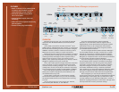
PS567A
PS580A
Manual switch
button
Ready
indicator
Activity
indicator
Network
port
COM/
RS-232 port
Master power
switch
Switched plugs and
plug indicators
Power circuit
A inlet and
circuit breaker
Power circuit
B inlet and
circuit breaker
NETWORK
ACT RDY
10BASE-T (DTE)
CONSOLE
RS-232
DEFAULT PLUG 1 PLUG 2 PLUG 3 PLUG 4 MASTER I/O 115V – 60Hz 15 AMPS MAX
Activity
indicator
Ready
indicator
Network
port
Circuit
breaker
Power
inlet
Master power
switch
Switched plugs and plug
indicators
Default
button
COM/RS-232
port