


5
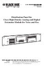
DISTRIBUTION PANEL
Installation
For safe operation, the patch panel first needs to be grounded. Follow these steps:
1. Strip one end of the 6 AWG copper ground wire to approximately 0.75”
(1.9 cm).
2. Crimp the ground wire to the ground lug; use a crimping tool of the
appropriate size.
3. Attach the ground lug to the patch panel using the two included pan-head
screws with captive locking washers (the flat washers and tooth washers).
Tighten the screws to a torque of 8 to 10 in.-lb. (0.9 to 1.1 N-m).
4. Connect the other end of the ground wire to a suitable grounding point at
your site.
Then install the panel:
CAUTION
Do not plug the cables into the top and bottom rows of connectors on
the panel’s middle and right side at the same time. Sliding the
mechanical door up or down prevents this from happening and guards
the attached equipment from damage. You can
use the panel’s eight left-
side connectors (both top and bottom rows) at the same time.
1. Place the panel at a level position on a rack or cabinet.
2. Using the supplied 10-32 or 12-24 screws, secure the panel to a 19" rack’s rails.
3. Install the RJ-11 and RJ-45 patch cables in the connectors on the panel’s
front.
4. Connect a telco cable to the RJ-21 connector on the panel’s back and the
telco connector on the proper Cisco card (part number EVM-HD-
8FXS/DID).
5. Route the cables, making sure that they are not tangled. (This will eliminate
crosstalk and attenuation.)